
Medical Device PCB Design: IPC-6012 Class 3 and Biocompatibility Standards
Medical device PCBs demand the highest reliability standards in electronics manufacturing. When designing circuit boards for life-sustaining equipment, understanding IPC-6012 Class 3 requirements and biocompatibility standards is mandatory. This guide explains what makes medical device PCBs different and how to ensure your designs meet regulatory requirements.
Why Medical Device PCBs Require Class 3 Standards
IPC-6012 Class 3 represents the most stringent acceptance criteria for rigid printed circuit boards. Unlike consumer electronics where occasional failures are tolerable, medical devices must function reliably throughout their service life. Class 3 applies to equipment where failure could endanger human life.
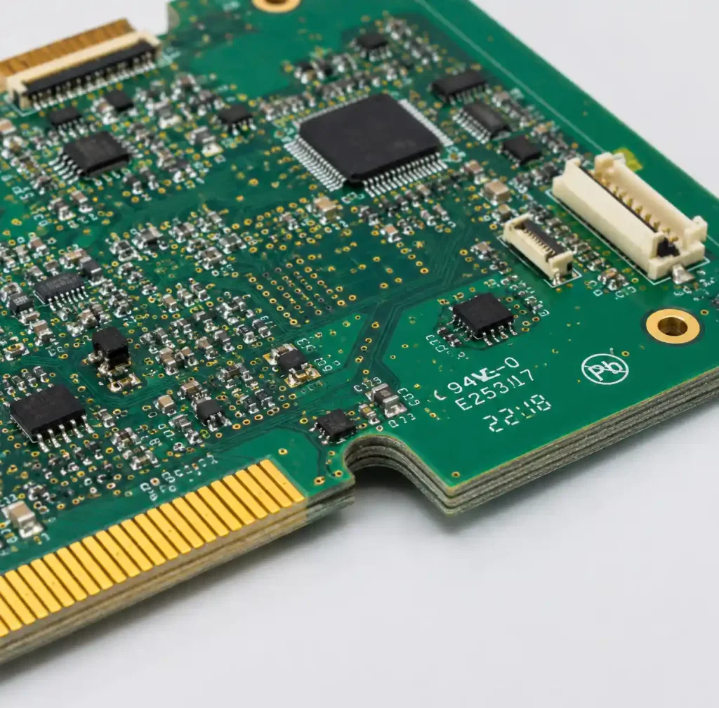
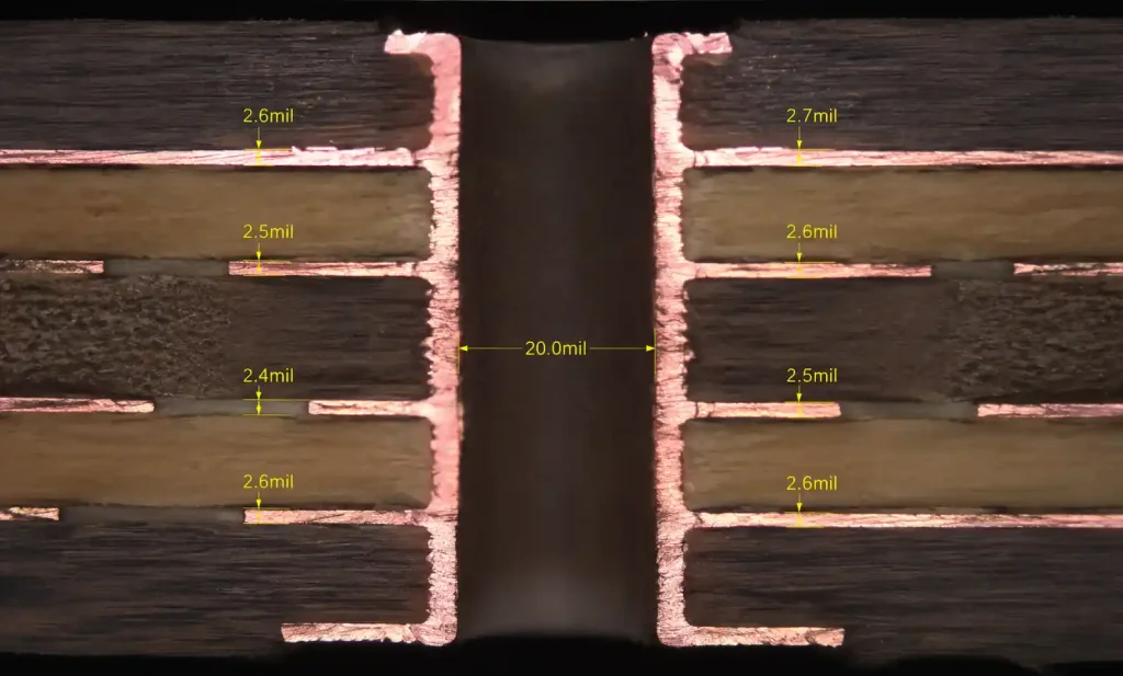
The core difference lies in manufacturing tolerances. Class 3 requires minimum 1.0 mil (25 μm) copper plating thickness in through-holes versus 0.8 mil (20 μm) for Class 2. Annular rings must measure at least 2.0 mils (50 μm) on all layers, double the Class 2 requirement. These specifications reduce the risk of open circuits, delamination, and thermal stress failures.
Medical device manufacturers specify Class 3 for implantable devices, patient monitoring systems, diagnostic equipment, and surgical instruments.
IPC-6012 Class 3 Critical Requirements
| Parameter | Class 2 | Class 3 | Impact on Medical Devices |
|---|---|---|---|
| Minimum plated through-hole copper | 0.8 mil (20 μm) | 1.0 mil (25 μm) | Prevents open circuits under thermal stress |
| Minimum annular ring | 1.0 mil (25 μm) | 2.0 mil (50 μm) | Ensures reliable via connections through product life |
| Etchback tolerance | 0.5-3.0 mils | 0.5-2.0 mils | Tighter control prevents resin recession issues |
| Maximum bow/twist | 1.5% | 0.75% | Critical for automated assembly and component stress |
| Internal void acceptance | 5% of connection | 0% (no voids) | Zero tolerance for connection reliability |
Class 3 boards undergo rigorous testing including microsectioning to verify plating thickness and annular ring measurements. Manufacturers maintain statistical process control (SPC) data proving consistent capability to meet Class 3 tolerances.
Medical device regulations mandate complete material traceability. Every copper foil lot, prepreg batch, and solder mask container must be documented with certificates of conformance, enabling recall capability if defects are discovered. High Tg FR-4 laminates rated for 170°C or higher provide thermal stability during assembly, sterilization, and operation.
Biocompatibility Standards for Medical PCBs
ISO 10993 provides the framework for evaluating biological safety of medical devices. PCBs in implantable devices require comprehensive biocompatibility testing. Pacemakers, neurostimulators, and cochlear implants incorporate PCBs that may contact body tissue or fluids.

ISO 10993-1 outlines biological evaluation categories: cytotoxicity, sensitization, irritation, systemic toxicity, genotoxicity, implantation effects, and hemocompatibility. Testing extent depends on contact duration and type.
Standard FR-4 laminates may not pass biocompatibility testing for implantable applications. Medical-grade conformal coatings provide a critical barrier between PCB materials and biological environments. Conformal coating materials like medical-grade silicone, parylene, or urethane must pass ISO 10993 testing and be applied uniformly without voids.
Design Considerations for Medical Devices
Medical device design begins with Design Failure Mode and Effects Analysis (DFMEA), identifying potential failure mechanisms and establishing controls. Common failure modes include solder joint fatigue, via barrel cracking, and component overstress.
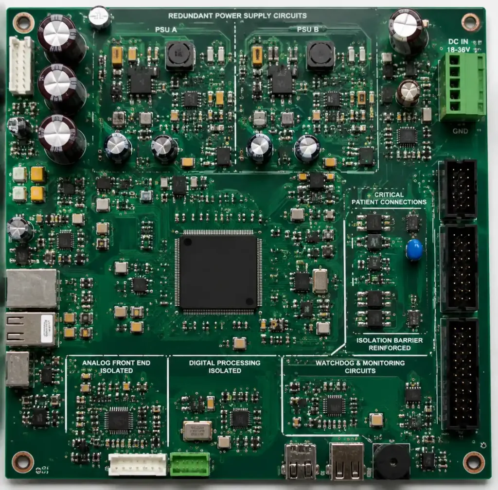
Redundancy strategies improve reliability: parallel current paths, redundant power supplies, and watchdog circuits. PCB stackup design impacts signal integrity and EMI performance—critical for medical devices operating near sensitive equipment.
Components require aggressive derating. Voltage, current, and power dissipation should operate at 50-70% of maximum ratings to extend lifetime and reduce failure probability.
| Component Type | Commercial Derating | Medical Device Derating |
|---|---|---|
| Ceramic capacitors | 50% voltage | 30-40% voltage |
| Electrolytic capacitors | 70% voltage, 80% temp | 50% voltage, 70% temp |
| MOSFETs | 80% voltage, 70% current | 60% voltage, 50% current |
Medical devices often operate in enclosed spaces with limited airflow. Thermal management must account for worst-case conditions. IEC 60601-1 specifies maximum touch temperatures: 48°C for metal surfaces, 60°C for non-metal surfaces.
FDA Regulatory Requirements
FDA’s Quality System Regulation (21 CFR Part 820.30) mandates design controls for Class II and III medical devices. PCB development must follow documented processes including design inputs, outputs, verification testing, validation, and design transfer.

Design History Files (DHF) contain all design documentation: schematics, layout files, PCB stackup documents, material specifications, test procedures, and validation reports. Device History Records (DHR) document each unit’s production including material lot numbers, PCB manufacturing process parameters, inspection results, PCB assembly work instructions, and conformal coating measurements.
Traceability enables rapid response to field failures. Manufacturers can identify affected lot codes and execute targeted recalls.
Sterilization Compatibility
Medical devices undergo sterilization before use. PCBs must survive the process without degradation.

Ethylene Oxide (ETO) is the most PCB-friendly method, operating at 37-63°C without stressing components. The process requires 12-24 hours plus aeration time.
Gamma radiation sterilization is convenient for large-scale production but can degrade polymers in substrates and conformal coatings. Semiconductor devices may experience parametric shifts at high doses. Specify radiation-resistant materials and verify component dose tolerance.
Autoclave sterilization uses steam at 121-134°C under pressure. Most electronic assemblies cannot withstand these conditions due to moisture penetration and thermal stress. Autoclave requires hermetically sealed enclosures.
Medical-grade conformal coating materials have documented sterilization compatibility. Parylene provides excellent moisture barrier and passes multiple sterilization cycles without degradation.
Quality Management and ISO 13485
ISO 13485 specifies quality management system requirements for medical device manufacturers. PCB suppliers serving medical customers maintain this certification, demonstrating capability to consistently meet regulatory requirements.

Contamination control is critical. PCB assembly in classified cleanroom environments (ISO Class 7 or 8) reduces particulate contamination that could cause failures. Implantable device assembly may require ISO Class 5 cleanrooms with strict particle count limits.
Class 3 PCBs undergo 100% electrical testing using flying probe or fixture testing. Visual inspection follows IPC-A-610 Class 3 criteria. AOI and X-ray inspection verify solder joint quality for HDI PCBs and BGAs. First article inspection includes microsectioning to verify plating thickness and via quality.
Cost and Lead Time Considerations
Class 3 medical device PCBs cost 30-50% more than equivalent Class 2 boards. Tighter tolerances, enhanced testing, comprehensive documentation, and material traceability drive higher costs. However, the investment is justified when weighed against regulatory compliance and patient safety.
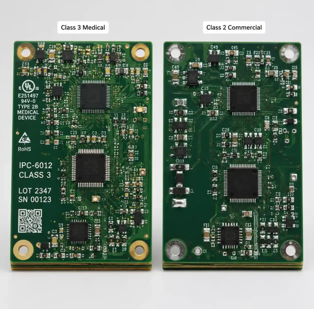
Lead times extend to 3-4 weeks for prototype medical PCBs versus 5-10 days for commercial boards. First article inspection and compliance documentation add time. Quick turn PCB assembly services can accelerate prototyping, but verify the assembler maintains Class 3 capability and ISO 13485 certification.
Selecting a Medical PCB Manufacturer
Choose manufacturing partners based on technical capability, quality systems, and regulatory compliance support—not just cost.
Essential qualifications include ISO 13485 certification, IPC-6012 Class 3 capability verified through first article reports, IATF 16949 certification for automotive medical devices, and IPC-A-610 Class 3 certified inspectors. Request statistical process control data for critical parameters.
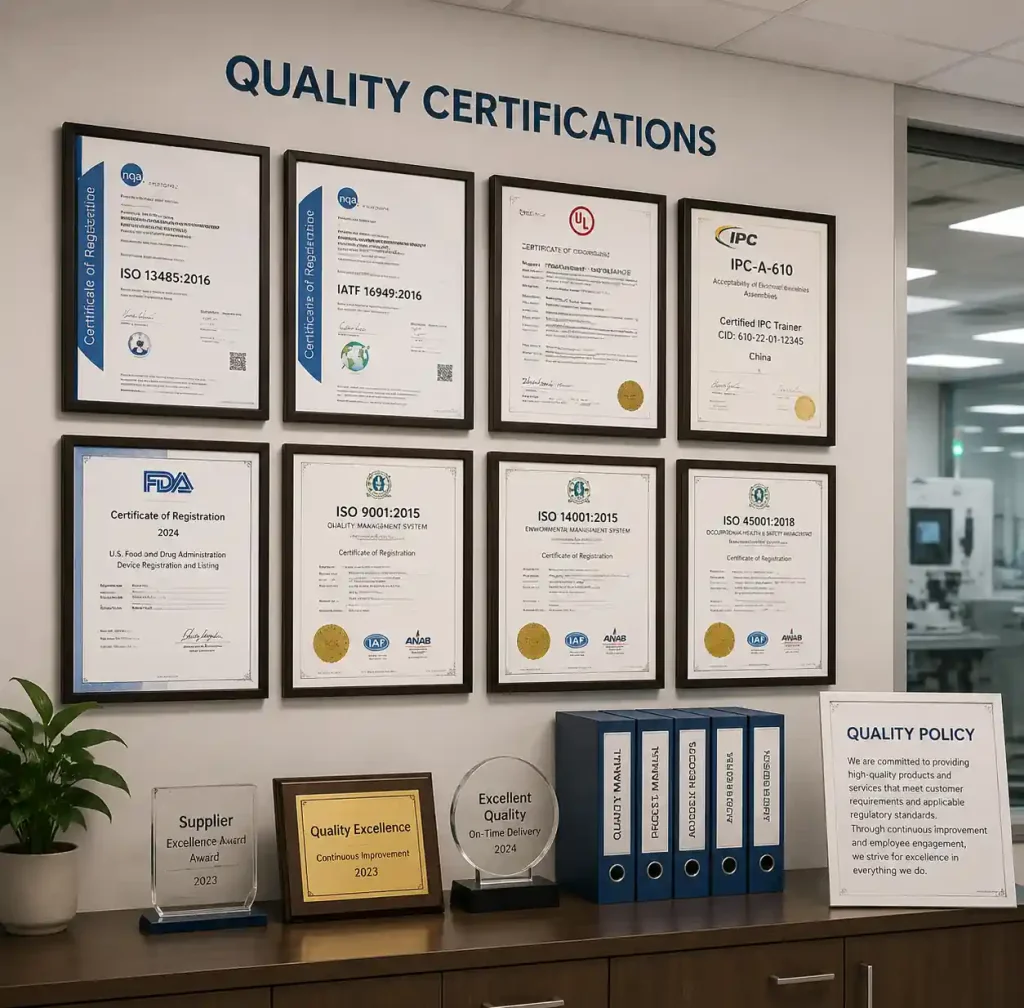
Medical device manufacturers need suppliers who understand design controls and support regulatory submissions. The PCB supplier should provide material certificates with traceability, process validation documentation, first article inspection reports with microsections, ongoing quality data with each shipment, and DFM review highlighting Class 3 concerns.
About Andwin Circuits: We maintain ISO 13485 and IATF 16949 certifications, specializing in medical equipment PCBs with IPC-6012 Class 3 capability. Our PCB assembly services include cleanroom capability, conformal coating, and comprehensive traceability documentation supporting FDA and international medical device regulations.
FAQ About Medical Device PCB Design
Q: What’s the difference between IPC Class 2 and Class 3 for medical devices?
Class 3 requires tighter tolerances: minimum 1.0 mil plated hole thickness versus 0.8 mil, 2.0 mil annular rings versus 1.0 mil, and zero tolerance for internal voids. Class 3 applies to life-sustaining medical devices where failure is unacceptable.
Q: Do all medical device PCBs need biocompatibility testing?
No. Biocompatibility testing per ISO 10993 is required only for devices with patient contact. Implantable devices require comprehensive testing. Equipment housings that isolate PCBs from patients may not require board-level testing.
Q: Can you use standard FR-4 laminate for medical device PCBs?
Yes, for most external medical devices. Standard FR-4 with high Tg (170°C+) meets IPC-6012 Class 3 requirements. Implantable devices may require medical-grade laminates. Conformal coating provides the primary biocompatibility barrier.
Q: How does sterilization affect PCB design choices?
Sterilization method determines material selection. ETO is compatible with most PCB materials. Gamma radiation requires radiation-resistant substrates and validated component dose tolerance. Autoclave is incompatible with standard PCB assemblies unless hermetically sealed.
Q: How long do medical device PCBs take to manufacture?
Expect 3-4 weeks for first article Class 3 medical PCBs including material procurement, fabrication, inspection, and documentation. Production orders typically ship in 2-3 weeks. Quick turn services can reduce time but verify Class 3 capability.
Conclusion
Medical device PCB design demands rigorous attention to reliability, regulatory compliance, and patient safety. IPC-6012 Class 3 standards establish the manufacturing quality baseline, while ISO 10993 biocompatibility requirements ensure materials are safe for patient contact. Success requires understanding FDA design controls, selecting qualified manufacturing partners, and building comprehensive documentation throughout development. The investment in Class 3 quality, medical-grade materials, and regulatory-compliant processes pays dividends in product reliability, regulatory approval speed, and reduced field failure risk. When patient lives depend on device performance, quality is non-negotiable.