
LED PCB Thermal Design: Heat Sink Integration and COB Technology
Every 10°C rise in LED junction temperature above rated maximum cuts lifespan nearly in half. This measured relationship between thermal management and reliability separates LED designs lasting 50,000 hours from those failing within the first year. Whether designing automotive headlamps, architectural lighting, or industrial fixtures, your PCB’s thermal architecture determines whether LEDs deliver rated lumen output or degrade prematurely.
This guide covers junction temperature control, substrate selection, heat sink attachment, and COB assembly to create LED systems meeting L70 performance targets.
Understanding LED Junction Temperature and Lumen Degradation
Junction temperature (Tj) determines LED reliability. Heat must travel through package, solder joint, PCB, thermal interface, heat sink, and to ambient air. Each interface contributes thermal resistance, measured in °C/W.
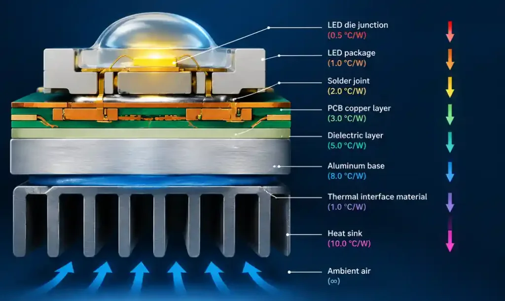
High-power LEDs specify maximum junction temperatures between 125°C and 150°C. For every 10°C reduction in junction temperature, LED lifespan approximately doubles. A white LED running at 105°C might achieve 50,000 hours to L70 (70% of initial lumen output), while at 85°C it exceeds 100,000 hours.
Primary degradation mechanisms—phosphor breakdown and die material diffusion—accelerate with temperature. Automotive LED applications demanding 15+ year lifespans in engine compartments reaching 105°C ambient require thermal management keeping junction temperatures 20-30°C below rated maximum.
MCPCB vs FR4: Thermal Performance Comparison
Standard FR4 PCBs have thermal conductivity around 0.3 W/m·K, making them thermal insulators. For LED power densities below 0.5W per LED, FR4 works if you design thermal vias underneath LED pads connecting to large copper pours. But this approach has limits.
Metal Core PCBs replace FR4 core with aluminum or copper base, dramatically improving heat transfer:
| Substrate Type | Thermal Conductivity | Typical Rθj-b (1W LED) | Junction Temp Rise | Cost Multiplier |
|---|---|---|---|---|
| Standard FR4 (1.6mm) | 0.3 W/m·K | 40-50 °C/W | +40-50°C | 1.0x |
| FR4 + Thermal Vias | 0.3 W/m·K | 25-35 °C/W | +25-35°C | 1.2x |
| Aluminum MCPCB (1.5 W/m·K) | 1.5 W/m·K | 12-16 °C/W | +12-16°C | 2.5x |
| Aluminum MCPCB (3.0 W/m·K) | 3.0 W/m·K | 8-12 °C/W | +8-12°C | 3.5x |
| Copper Core PCB | 8-10 W/m·K | 5-8 °C/W | +5-8°C | 5-8x |
Thermal resistance from junction to board (Rθj-b) directly translates to temperature rise. A 1W LED on standard FR4 with 45°C/W runs 45°C hotter than board temperature. On aluminum MCPCB with 10°C/W, that LED runs only 10°C above board temperature—a 35°C improvement doubling lifespan.
MCPCB construction places thin dielectric (50-200μm) between copper circuit layer and aluminum base. Dielectric thermal conductivity determines overall performance. Standard dielectrics offer 1.0-2.0 W/m·K; high-performance versions reach 3.0-5.0 W/m·K.
COB Technology: Direct Die Attachment Benefits
Chip-on-Board (COB) eliminates packaged LED components. Bare LED dice are wire-bonded or flip-chip mounted directly to substrate, then encapsulated with phosphor-silicone. This removes two thermal interfaces: LED package substrate and solder joint.
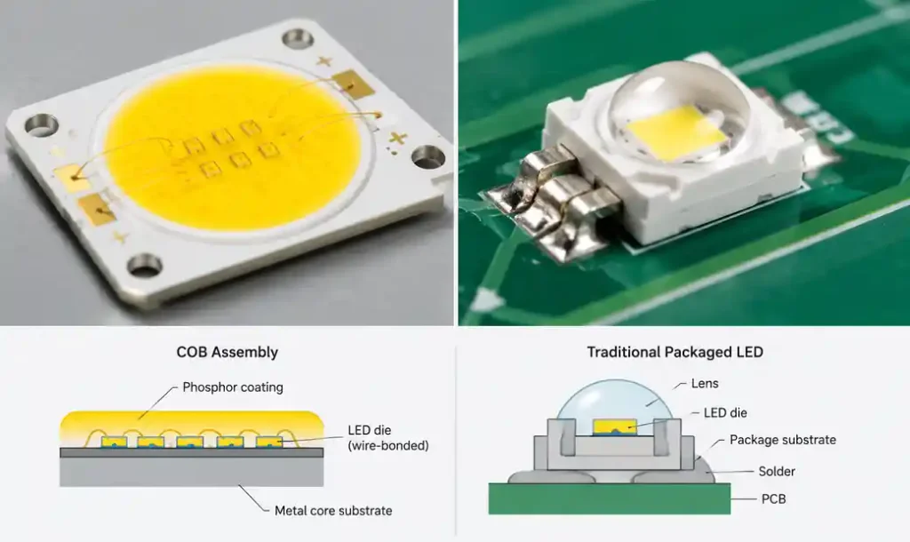
Standard mid-power LED packages have internal thermal resistance (Rθj-c) of 8-15 °C/W. COB reduces this to 2-5 °C/W because die sits directly on conductive substrate. For 10W LED arrays, this 10°C/W reduction means 100°C less temperature rise.
COB enables higher packing densities. Without physical footprint of individual packages, dice can be placed 2-3mm apart versus 5-10mm, creating uniform light critical for automotive headlamps.
Manufacturing tradeoff is complexity. For volumes below 10,000 units annually, packaged LEDs offer better economics. Above 50,000 units, COB’s material cost savings (bare dice cost 30-50% less) and thermal performance justify investment.
Heat Sink Attachment Methods and Thermal Interface Materials
The interface between PCB and heat sink often contributes 20-40% of total thermal resistance. Getting this wrong negates benefits of expensive MCPCB substrates.
| Attachment Method | Thermal Resistance | Assembly Complexity | Rework Capability | Typical Applications |
|---|---|---|---|---|
| Thermal Paste (Silicone) | 0.5-1.0 °C·cm²/W | Low | High | Prototypes, low-power |
| Thermal Pad (Gap Filler) | 1.0-2.0 °C·cm²/W | Low | High | Consumer electronics |
| Phase Change Material | 0.3-0.6 °C·cm²/W | Medium | Low | Automotive, industrial |
| Thermally Conductive Adhesive | 0.4-0.8 °C·cm²/W | Medium | None | Permanent assemblies |
| Thermal Grease (High-Performance) | 0.2-0.4 °C·cm²/W | Medium | High | High-power LED fixtures |
Thermal paste remains most common TIM. Apply thin, uniform layer (50-100μm) between MCPCB bottom and heat sink. Thicker applications increase thermal resistance because paste has moderate conductivity (2-5 W/m·K).
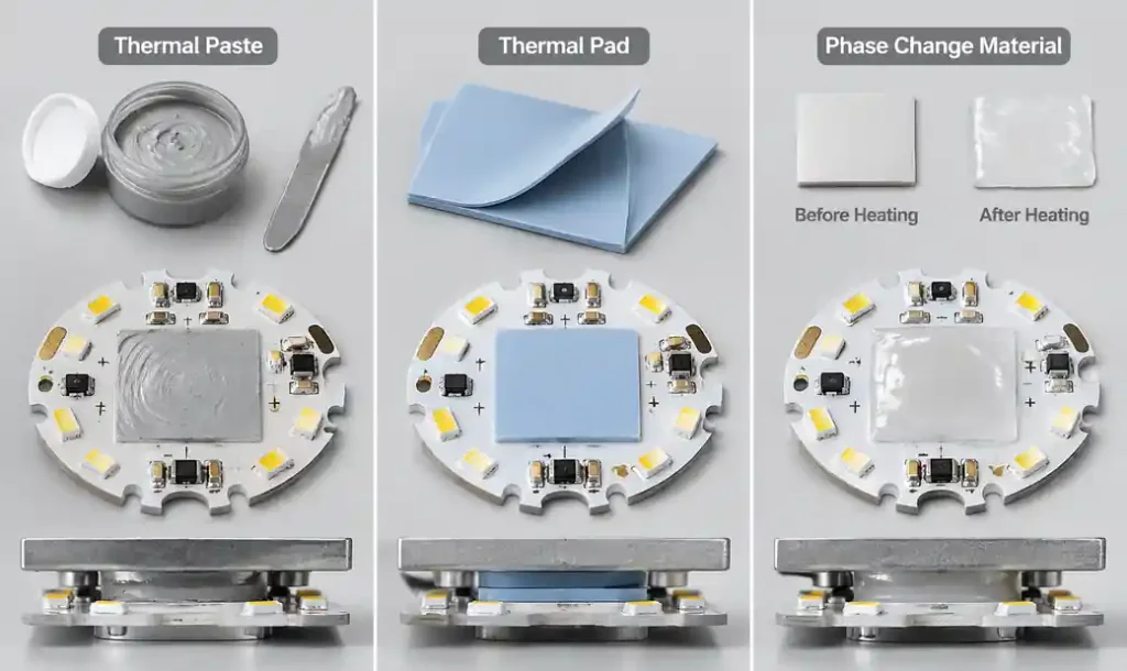
Phase change materials (PCM) start solid at room temperature but soften at 45-65°C, conforming to surface irregularities as LED heats up. Automotive LED modules frequently specify PCM because it maintains consistent performance through thermal cycling.
Measure heat sink flatness. Aluminum extrusions often have 50-100μm surface variation. Machined surfaces achieve 10-20μm flatness. Pairing poorly machined heat sink with thin thermal grease creates air gaps acting as thermal insulators.
Thermal Simulation and Design Validation
Thermal simulation using FEA tools like ANSYS Icepak or Solidworks Flow Simulation identifies problems before building prototypes.
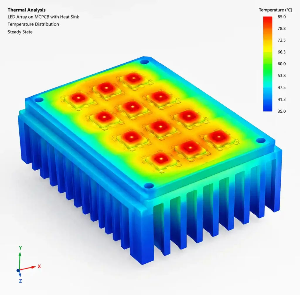
Start with accurate boundary conditions. LED manufacturers provide thermal models. PCB layer stackup, copper weight, and dielectric thermal conductivity affect heat spreading. Define properties carefully—assuming FR4 at 0.3 W/m·K when using 0.15 W/m·K laminate under-predicts junction temperature by 15-20°C.
Model heat sink geometry including fin spacing and airflow. Natural convection provides 5-10 W/m²·K heat transfer; forced airflow at 1 m/s increases this to 15-25 W/m²·K.
Validate simulation against measurements. If measured values exceed simulation by more than 10%, review material properties.
Design Rules for Automotive LED Thermal Management
Automotive applications subject LEDs to harsh conditions: -40°C to +105°C ambient, 3000+ hour salt spray, continuous vibration, and 15-year lifespan requirements.
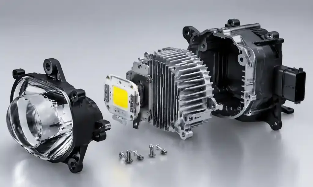
AEC-Q101 qualification requires LED components to survive accelerated stress including thermal shock (-40°C to +150°C, 1000 cycles) and high-temperature storage (+150°C, 1000 hours). PCB thermal design must keep junction temperatures low enough to avoid lumen degradation.
Practical guidelines: maintain junction temperature below 105°C at 85°C ambient; design thermal paths working in horizontal and vertical mounting; specify MCPCB with dielectric ≥2.0 W/m·K; use phase change TIM; provide heat sinks with forced airflow or large convection area (>150 cm² per 10W).
Lumen Maintenance and L70 Lifetime Prediction
L70 is the operating time until lumen output degrades to 70% of initial value. Commercial lighting specifies L70 at 50,000 hours; automotive demands 15,000+ hours.
Phosphor degradation dominates lumen loss in white LEDs. High temperatures accelerate chemical changes in phosphor. This follows an Arrhenius relationship—every 10°C increase roughly doubles degradation rate.
LED manufacturers provide TM-21 projection data showing lumen maintenance at multiple temperatures. Use this to predict field performance. If testing shows L70 at 55,000 hours when operating at 85°C and your design achieves 75°C, expect L70 to exceed 100,000 hours.
Manufacturing tolerances in TIM application, heat sink flatness, and LED binning can add 10-15°C to real-world junction temperatures. Design for 80-85°C to provide margin.
Optimizing Copper Weight and Thermal Via Design
MCPCB circuit copper weight affects current-carrying capacity and heat spreading. Standard MCPCB copper is 1oz (35μm), adequate for LED currents up to 1-2A per trace. High-power arrays requiring 5A+ benefit from 2oz or 3oz copper.
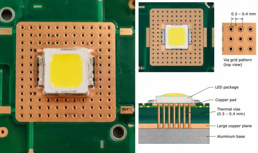
Thermal vias matter even on MCPCB. Vias through dielectric to aluminum core reduce thermal resistance by 10-20%. Place 0.3mm diameter vias on 1mm grid underneath each LED pad.
For FR4 LED designs, thermal vias are essential. Best practices: via diameter 0.3-0.4mm, spacing 0.8-1.2mm in grid pattern, connecting to large copper pours, copper plating.
Heat Sink Integration: Mechanical and Thermal Considerations
Heat sink design interacts with PCB thermal design. Aluminum MCPCB with 10 °C/W thermal resistance requires heat sink with similar or better performance.
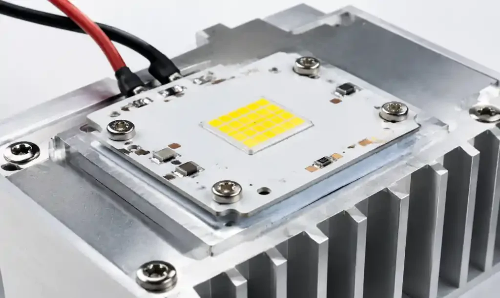
Heat sink thermal resistance (Rθh-a) depends on surface area, fin geometry, and airflow. Passive extruded aluminum in natural convection provides 1-3 °C/W per 10W. Forced airflow at 1-2 m/s reduces this to 0.5-1.0 °C/W per 10W.
Size heat sinks using total power. If LED array dissipates 20W and you need junction temperature below 100°C with 50°C ambient, you have 50°C budget. Subtracting Rθj-b (10°C) and Rθb-h (2°C) leaves 38°C for heat sink. Rθh-a must be ≤1.9 °C/W.
Black anodized heat sinks improve radiative heat transfer by 15-25% and provide corrosion resistance for outdoor and automotive applications.
FAQ
Q: Can I use standard FR4 PCB for LED lighting, or is MCPCB always necessary?
For low-power LEDs (below 0.5W per LED) with adequate spacing and thermal via design, FR4 provides acceptable performance. However, MCPCB offers significantly lower junction temperatures—typically 20-30°C cooler—doubling LED lifespan. For commercial or automotive applications, MCPCB justifies its 2-3x higher cost through reduced warranty claims. High-power LEDs above 1W per die nearly always require MCPCB or ceramic substrates. Check out our Metal Core PCB and MCPCB capability pages for detailed specifications.
Q: What thermal conductivity should I specify for MCPCB dielectric layer?
Standard MCPCB dielectrics provide 1.0-1.5 W/m·K and work for moderate-power designs (5-15W total). For high-power automotive or industrial applications, specify high-performance dielectrics at 2.0-3.0 W/m·K. Cost premium is 20-40% but reduces junction temperature by 10-15°C. If design shows junction temperatures within 10°C of maximum rating, upgrading dielectric thermal conductivity provides essential margin. Learn more about thermal management solutions for LED applications.
Q: How do I choose between thermal paste, phase change material, and thermal pads?
Thermal paste offers lowest thermal resistance (0.2-0.5 °C·cm²/W) but requires careful application. Ideal for prototypes where rework is expected. Phase change materials provide consistent performance through thermal cycling and are standard in automotive (0.3-0.6 °C·cm²/W). Thermal pads (1.0-2.0 °C·cm²/W) work for low-power consumer electronics where assembly ease matters more than ultimate thermal performance.
Q: What junction temperature should I target for 50,000-hour LED lifespan?
LED manufacturers specify maximum junction temperatures of 125-150°C, but operating continuously at these limits severely reduces lifespan. For 50,000+ hour L70 lifetime, target junction temperatures no higher than 85-95°C. If your application experiences high ambient temperatures (above 50°C), reduce targets to 75-85°C. Every 10°C reduction approximately doubles LED lifespan.
Q: Is COB technology worth the manufacturing complexity?
COB delivers superior thermal performance and higher packing density but requires specialized assembly equipment. For volumes below 10,000 units annually, packaged LEDs offer better economics. Above 50,000 units, COB’s lower material cost (30-50% less) and thermal advantages justify manufacturing investment, particularly in automotive and high-power applications where junction temperature limits are tight.
Conclusion
LED thermal management begins at the PCB and determines whether lighting products meet lifetime targets or fail prematurely. Junction temperature control through proper substrate selection, heat sink integration, and thermal interface materials is essential for high-power or long-life applications. MCPCB substrates provide 3-5x better thermal performance than FR4, translating to lower junction temperatures and extended L70 lifetimes. Design margin is insurance—target junction temperatures 15-20°C below maximum ratings to absorb manufacturing variations. The difference between designs achieving 50,000-hour L70 lifetime versus those degrading in 20,000 hours often comes down to 10-15°C junction temperature—entirely achievable through proper PCB thermal design and heat sink integration.