
Military PCB Standards: MIL-PRF-31032 and MIL-PRF-55110 Compliance
Defense and aerospace electronics demand a level of reliability that consumer products never approach. According to the Defense Logistics Agency, PCBs used in military applications undergo more than twice the testing required by commercial standards, with field failure rates that must remain below 0.01% over 15-25 year operational lifespans. A single circuit board failure in a radar system, weapons platform, or avionics can cost millions in downtime and potentially endanger missions.
If you want to manufacture PCBs for military contracts, then you will need to understand MIL-PRF-31032 and MIL-PRF-55110—the two core military specifications that govern design, fabrication, testing, and qualification. This guide explains these standards, their differences from commercial specifications, and how to achieve compliance for defense-grade circuit boards.
What Are Military PCB Standards?
Military PCB standards are DoD performance specifications for printed circuit boards used in defense and aerospace applications. These exceed commercial IPC requirements through stricter process controls, continuous qualification, and comprehensive documentation.
MIL-PRF-31032: Active specification for rigid and flexible PCBs, covering single-layer through multilayer boards. Approved for all DoD departments.
MIL-PRF-55110: Legacy specification for rigid multilayer boards, declared “Inactive for New Design” in 1998. Referenced for existing programs only.
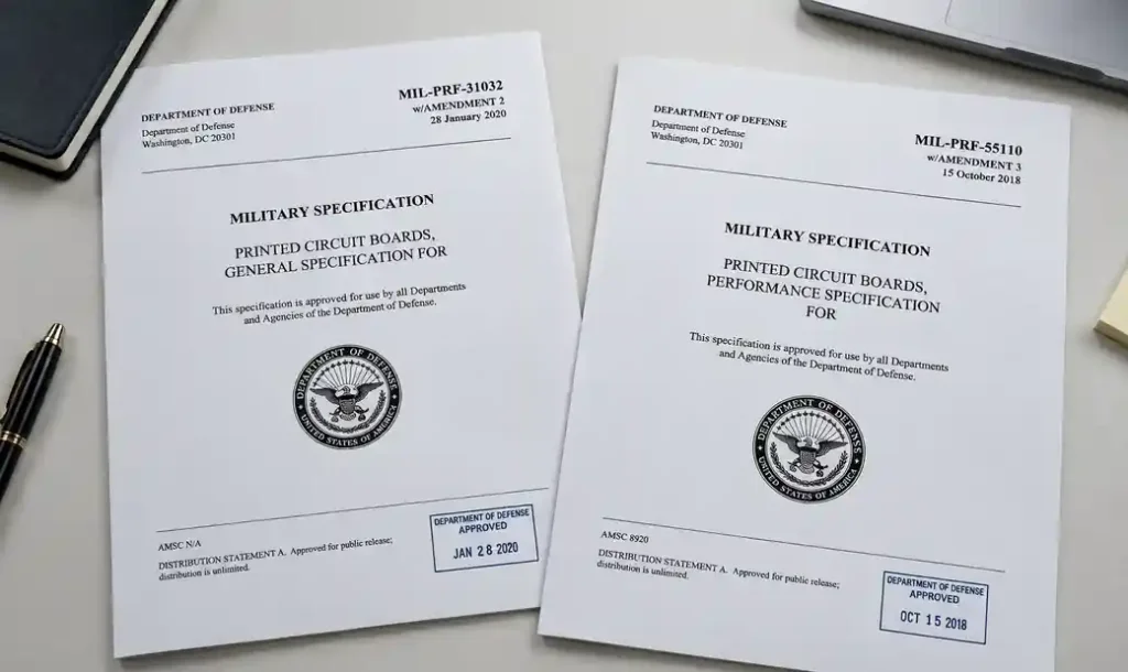
MIL-PRF-31032: Current Military PCB Standard
MIL-PRF-31032 is the current DoD performance specification that replaced MIL-PRF-55110 for new military PCB designs. The standard uses specification sheets to define requirements for different board types:
Specification Sheet Breakdown
| Specification Sheet | Board Type | Key Requirements |
|---|---|---|
| MIL-PRF-31032/2 | Rigid single/double layer, thermosetting resin | PTH or non-PTH, soldered part mounting |
| MIL-PRF-31032/3 | Flexible single/double layer | With/without PTH, with/without stiffeners |
| MIL-PRF-31032/6 | High-frequency rigid boards | Thermoplastic or thermosetting, optional external heat sink |
The standard allows mixed material boards (thermoplastic and thermosetting), boards with internal metal cores, and external heat sinks for thermal management applications.
Performance-Based Approach
Unlike prescriptive commercial standards that define specific processes, MIL-PRF-31032 uses a performance-based approach. Manufacturers must prove process capability through qualification testing and maintain that capability continuously. This flexibility allows manufacturers to use commercial best practices while meeting military performance requirements.
MIL-PRF-55110: Legacy Standard for Multilayer Boards
MIL-PRF-55110 covered rigid boards including multilayer configurations. Type 3 referred to multilayer boards with plated through holes. The DoD phased it out in 1998 due to overlap with IPC-6012 Class 3, inflexibility, and supply chain limitations. Existing programs continue using MIL-PRF-55110 for lifecycle support, but new projects must use MIL-PRF-31032 or IPC-6013 Class 3.

Military Spec vs IPC Class 3: Key Differences
Many engineers assume IPC-6012 Class 3 and military specifications are identical. They’re not. Understanding these differences is critical for defense contract compliance.
| Aspect | IPC-6012 Class 3 | MIL-PRF-31032 |
|---|---|---|
| Qualification | Product inspection only | Process qualification + continuous monitoring |
| Supplier status | Any certified manufacturer | Qualified Products List (QPL) required |
| Documentation | Standard manufacturing records | Full traceability with material certifications |
| Testing | Sample-based acceptance | Destructive testing + microsectioning required |
| Process control | Manufacturer’s discretion | DoD-approved process controls |
| Change management | Manufacturer discretion | Government approval for process changes |
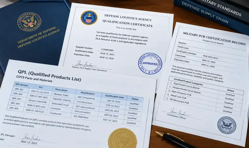
Qualified Products List (QPL)
For many military programs, manufacturers must appear on the Qualified Products List maintained by the Defense Logistics Agency. QPL qualification requires:
- Initial qualification testing of production samples
- On-site process audits
- Demonstrated process capability (Cpk ≥ 1.33)
- Continuous monitoring and periodic re-qualification
- DPAS (Defense Priorities and Allocations System) registration
Manufacturers can search the QPL database at the DLA’s quicksearch portal to verify supplier status and review qualification requirements.
Class 3 Acceptance Criteria for Military PCBs
Class 3 acceptance criteria define the highest reliability level for electronic assemblies where continued performance is critical and equipment downtime cannot be tolerated. Military PCBs must meet or exceed these requirements.
Visual Inspection Requirements
- Zero cosmetic defects in functional areas
- Minimum annular ring: 0.002″ (0.05mm) after etch and plate
- Registration tolerance: ±0.004″ (0.10mm) for multilayer boards
- Hole quality: No nicks, burrs, or resin smear in plated through holes
- Copper thickness: 25% above nominal specification minimum
Electrical Testing
- 100% electrical continuity testing (no sampling)
- Hipot testing at 2× operating voltage + 1000V AC
- Controlled impedance verification with TDR measurement (±10% tolerance)
- Isolation resistance: >50MΩ at 100VDC after environmental conditioning
Destructive Testing and Microsectioning
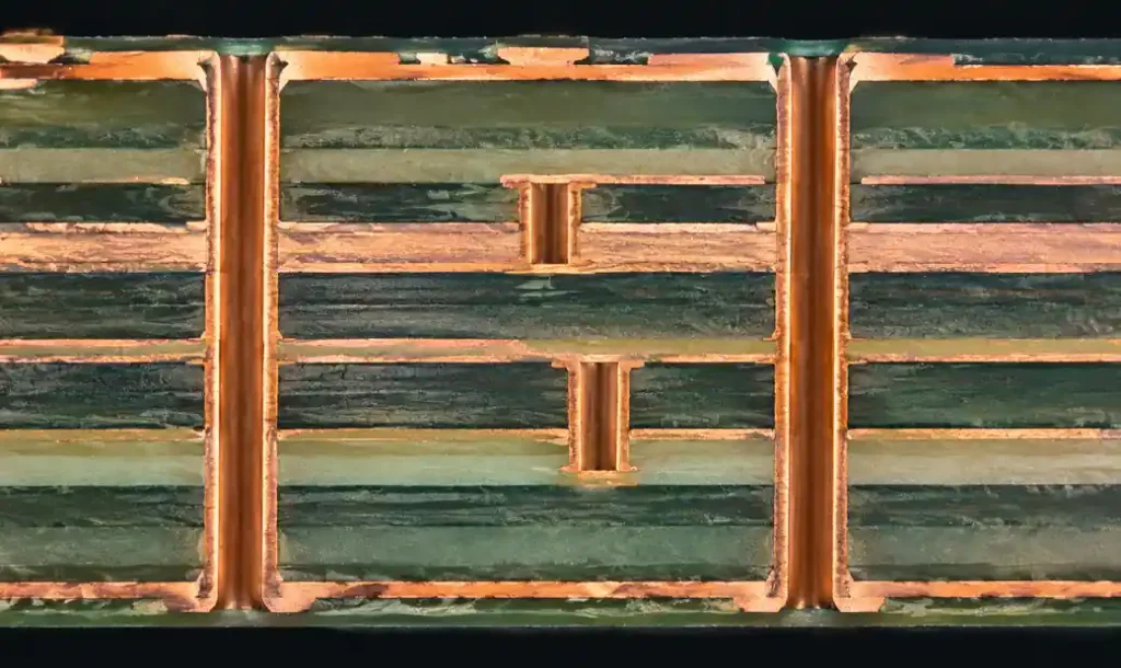
Military PCB qualification requires destructive analysis beyond commercial Class 3. Microsectioning reveals internal structures invisible to external inspection:
- Plating thickness: Minimum 1 mil (25µm) barrel, 1.4 mils (35µm) at hole edges
- Internal voids: Maximum 5% void area in solder joints
- Delamination: Between copper and dielectric layers
- Crack formation: In solder joints or copper
Cracks fail when exceeding 75% of joint dimension. Multiple defects automatically fail regardless of individual severity.
Thermal Stress Testing
Samples undergo thermal cycling before microsectioning: 288°C solder float (10 seconds), 260°C reflow simulation (6 cycles), and thermal shock -55°C to +125°C (500 cycles). Zero delamination, blistering, or copper separation permitted.
Material Certifications and Documentation
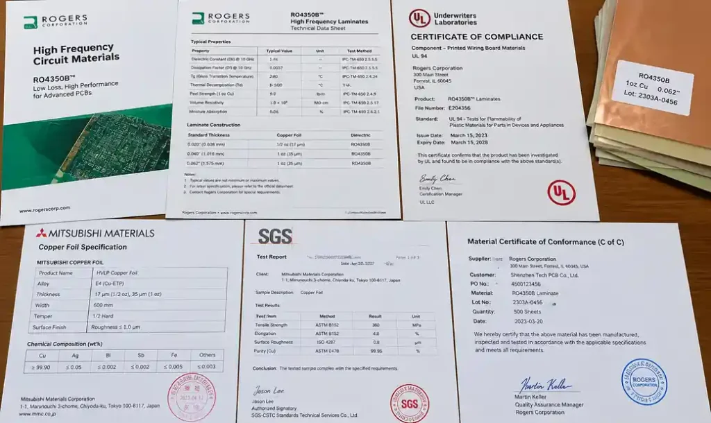
Military PCB contracts require complete material traceability. Every laminate, prepreg, and copper foil needs:
- UL recognition (typically UL 796)
- Certificate of Conformance from suppliers
- Lot traceability to finished board serial numbers
- Glass transition temperature (Tg) ≥170°C by DSC testing
- Decomposition temperature (Td) ≥340°C
- Z-axis CTE <70 ppm/°C through Tg
- Dk and Df values for controlled impedance boards
Some programs require conflict minerals declarations and DFARS compliance.
Operating Environment Requirements
Military PCBs survive environmental extremes through qualification testing:
Temperature: -55°C to +125°C operating, -65°C to +150°C storage, 500-1000 thermal cycles, 20°C/minute rate changes.
Humidity and Salt Fog: 90-95% RH at 65°C for 240 hours, 5% NaCl salt fog at 35°C for 96 hours per ASTM B117. Must maintain >50MΩ isolation resistance post-exposure.
Vibration and Shock: 0.04 g²/Hz random vibration 20-2000 Hz for 4 hours per axis (MIL-STD-810), 50g half-sine shock pulse with functional testing during and after exposure.
DPAS Ratings and Defense Priorities
The Defense Priorities and Allocations System (DPAS) gives DoD contracts priority for materials and manufacturing capacity. When you receive a defense contract with a DPAS rating, you must prioritize it above commercial orders.
DPAS Rating Levels
- DX rating: Highest priority, typically for urgent military or national defense programs
- DO rating: Standard defense priority, used for most military procurement contracts
Suppliers must accept and schedule DPAS-rated orders ahead of unrated commercial work. Failure to comply can result in penalties and loss of defense contracting eligibility.

How to Achieve Military PCB Compliance
Transitioning to military-grade PCB production requires process upgrades and quality system changes.
Step 1: Gap Analysis
Compare current capabilities against specification requirements. Review IPC-6012 Class 3 status, identify processes needing DoD approval, assess testing equipment, evaluate material suppliers, and check documentation systems for traceability.
Step 2: Implement Process Controls
Document all critical processes with acceptance criteria. Establish 100% material inspection, SPC for plating thickness and registration, environmental monitoring in production areas, and NIST-traceable equipment calibration.
Step 3: Qualification Testing
Produce qualification lot (25-50 boards), complete electrical testing, submit for destructive testing and microsectioning, finish environmental stress testing, and document results with photographs and measurements.
Step 4: QPL Application
Submit qualification data to DSCC, schedule on-site audit, demonstrate process capability (Cpk ≥ 1.33), obtain DPAS registration, and maintain qualification through periodic re-testing.
Choosing Between MIL-PRF-31032 and IPC-6013 Class 3
The DoD accepts IPC-6013 Class 3 (C) as a commercial equivalent to MIL-PRF-31032 for many programs, providing a more accessible path without full MIL-spec qualification.
Use MIL-PRF-31032 when: Contract specifies it, QPL listing required, extreme environments (space, underwater, weapons), or long-term DoD supplier relationship is strategic.
Use IPC-6013 Class 3 (C) when: Contract allows COTS alternatives, timeline doesn’t permit QPL qualification, commercial supplier base preferred, or reliability needs are high but not extreme.
Confirm specification requirements with your contracting officer.
Frequently Asked Questions
What’s the difference between IPC-6012 Class 3 and military spec PCBs?
IPC-6012 Class 3 focuses on product acceptance criteria through inspection, while military specifications like MIL-PRF-31032 require continuous process qualification, full material traceability, destructive testing, and often QPL listing. Military specs also mandate environmental testing beyond commercial standards and require government approval for process changes.
Can a commercial PCB manufacturer make military-grade boards without QPL qualification?
Yes, if the contract allows IPC-6013 Class 3 (C) as an equivalent or doesn’t specifically require QPL listing. However, manufacturers must still meet stricter documentation, testing, and traceability requirements compared to standard commercial production. ITAR registration may also be required depending on the application.
How long does QPL qualification take for military PCBs?
Initial QPL qualification typically takes 6-12 months from application submission to approval. This includes qualification lot production (4-8 weeks), full testing and microsectioning (6-10 weeks), DLA review (8-12 weeks), and on-site audit scheduling. Plan for longer timelines if process deficiencies are identified during qualification.
Is MIL-PRF-55110 still used for any military programs?
MIL-PRF-55110 remains active for lifecycle support of existing military systems designed before 1999, but all new designs must use MIL-PRF-31032 or IPC-6013 Class 3. Some legacy programs continue referencing MIL-PRF-55110 to maintain configuration control, but the specification is no longer updated or maintained by the DoD.
What materials are required for military PCB construction?
Military PCBs require high-Tg FR-4 laminates (Tg ≥170°C), polyimide for flex circuits, or Rogers for RF applications. All materials need UL 796 recognition and CTE <70 ppm/°C. DFARS compliance may be required.
How much more do military spec PCBs cost compared to commercial boards?
Military-grade PCBs cost 2-5× more than commercial Class 2 boards due to stricter materials, additional testing including destructive analysis, comprehensive documentation, and lower volumes. Lead times are also 2-4 weeks longer for qualification testing.
Conclusion
Military PCB standards MIL-PRF-31032 and MIL-PRF-55110 establish the performance requirements, testing protocols, and documentation necessary for defense-grade circuit boards. MIL-PRF-31032 has replaced MIL-PRF-55110 as the active specification for new military designs, offering a performance-based approach that allows commercial manufacturing practices while ensuring defense-level reliability.
Achieving compliance requires more than meeting IPC Class 3 acceptance criteria. Manufacturers must implement continuous process qualification, complete material traceability, destructive testing, and environmental stress testing that goes beyond commercial standards. For programs requiring Qualified Products List status, additional qualification testing and periodic audits are mandatory.
If your project requires military-grade PCBs, Andwin Circuits provides Class 3 manufacturing with full traceability and documentation. Our certifications include ISO 9001, UL, and IATF 16949, and we support both commercial and defense applications requiring enhanced reliability. Contact our team to discuss your military PCB requirements and compliance pathway.