
Aerospace PCB Requirements: AS9100 and IPC-6012 Class 3 Standards
The aerospace PCB market reached $1.8 billion in 2025, with commercial space launches requiring over 450,000 square meters of high-reliability circuit boards annually. Unlike commercial electronics, aerospace PCBs operate where a single failure can compromise an entire mission or aircraft system.

This guide covers aerospace PCB qualification requirements: AS9100 quality management, IPC-6012 Class 3 acceptance criteria, material selection for extreme temperatures, testing protocols, and ITAR compliance for defense applications.
Understanding AS9100 for PCB Manufacturing
AS9100 is the aerospace quality management standard built on ISO 9001, adding requirements critical to aviation, space, and defense supply chains. For PCB manufacturers, AS9100 certification demonstrates complete control over materials, processes, traceability, and documentation.
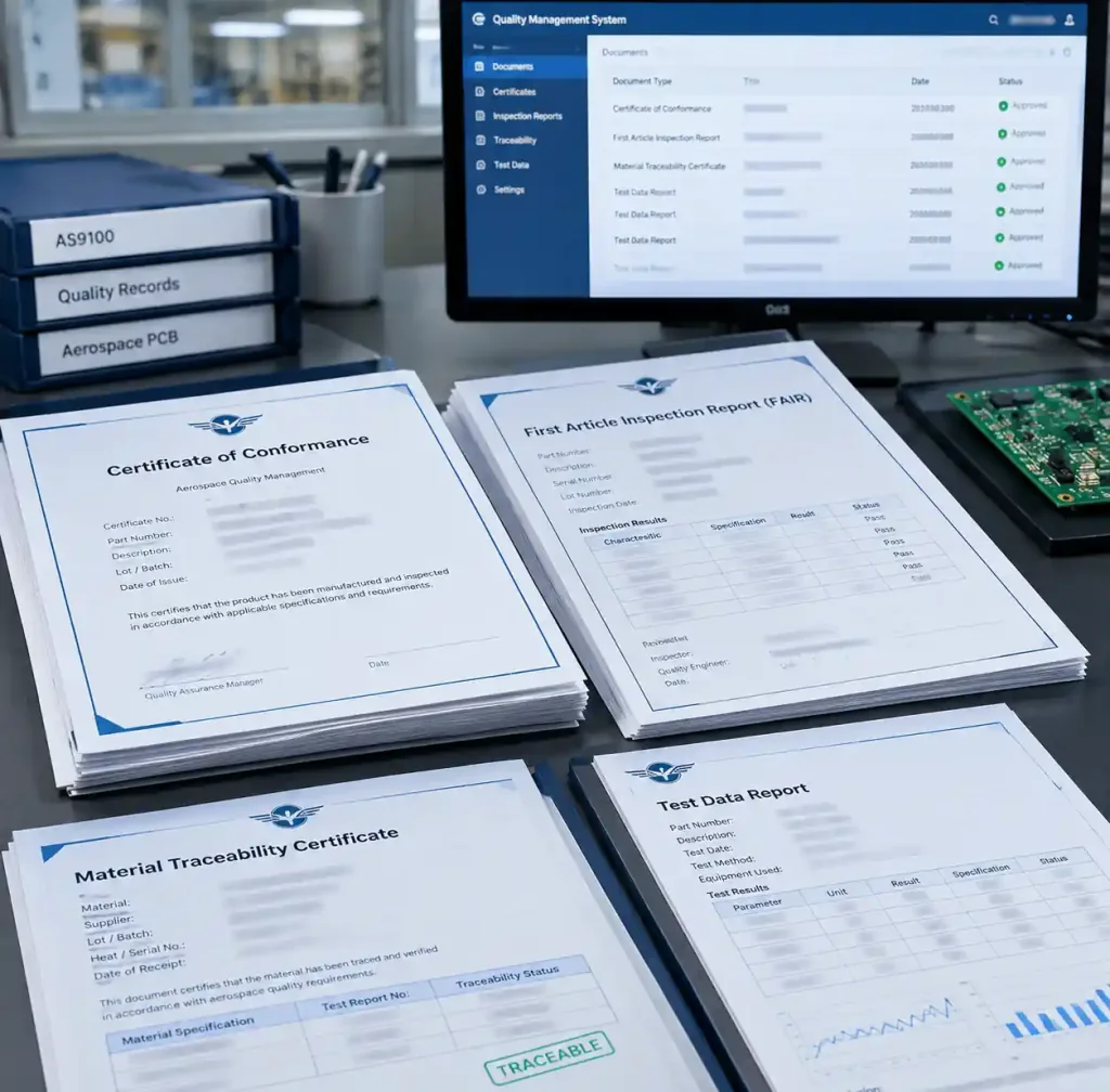
AS9100 requires material traceability from raw laminate through finished board. Manufacturers maintain certificates of conformance showing material composition, flame rating, and electrical properties for every lot. This becomes critical during failure analysis—boards failing in-service trace back to specific resin batches used months earlier.
Process control extends beyond ISO 9001 requirements. Manufacturers validate critical processes like lamination profiles, plating bath chemistry, and drill bit wear limits. Environmental monitoring of temperature and humidity during production is mandatory. First article inspection reports document new designs meet specifications before volume production.
IPC-6012 Class 3: The Baseline for Aerospace
IPC-6012 defines qualification standards for rigid PCBs. Class 3 represents the highest reliability tier for applications where continued performance is critical and equipment downtime cannot be tolerated.
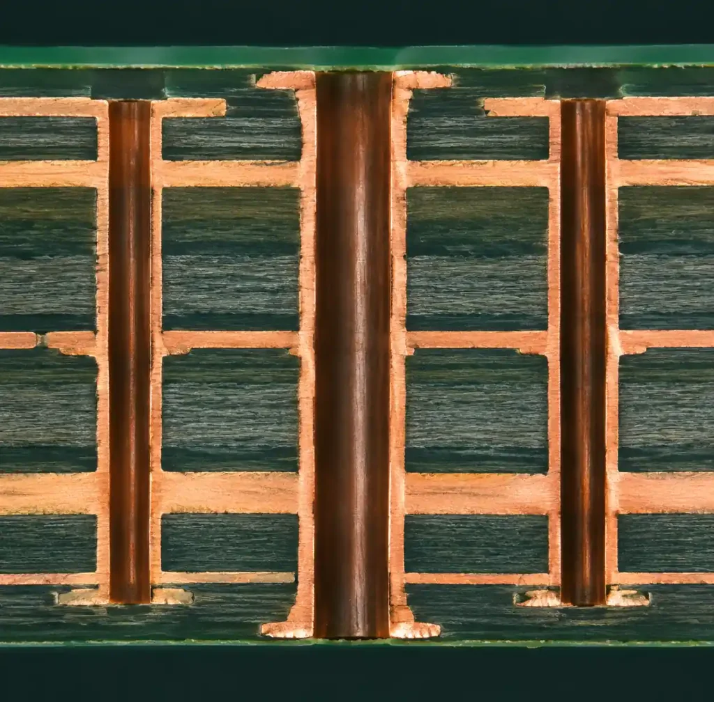
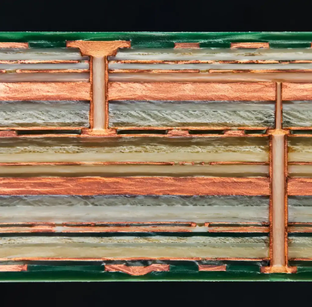
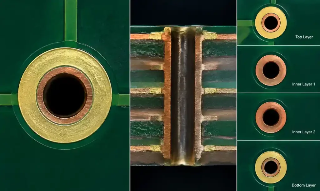
The distinction between Class 2 (general industrial) and Class 3 appears in every fabrication step. Class 3 allows zero drill breakouts—drilled holes must stay within capture pads on every layer. Minimum annular ring is 2 mils (50μm) versus 1 mil for Class 2. Barrel copper plating must reach 25μm minimum, compared to 20μm for Class 2.
Visual inspection criteria are stricter. Class 3 rejects boards with any measles (white spots indicating delamination), scratches deeper than 10% of conductor thickness, or lifted lands. Microsection analysis of test coupons becomes mandatory.
| Parameter | IPC Class 2 | IPC Class 3 | Improvement |
|---|---|---|---|
| Minimum Annular Ring | 1 mil (25μm) | 2 mils (50μm) | 100% increase |
| Barrel Plating | 20μm minimum | 25μm minimum | +25% thickness |
| Drill Breakout | Allowed if 50% annular ring remains | Zero breakout tolerance | Complete elimination |
| Microsection Testing | Sample-based | 100% coupon inspection | Full verification |
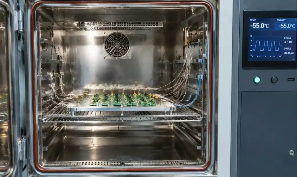
Class 3A adds space and military avionics requirements: enhanced thermal cycling (-55°C to +125°C for 500 cycles), controlled plating processes, and stricter surface finish uniformity criteria.
Material Selection for Extreme Operating Conditions
Aerospace applications demand PCB materials maintaining electrical and mechanical properties across temperature extremes, surviving vibration and shock, and resisting moisture in unpressurized environments.
High-Temperature Laminates
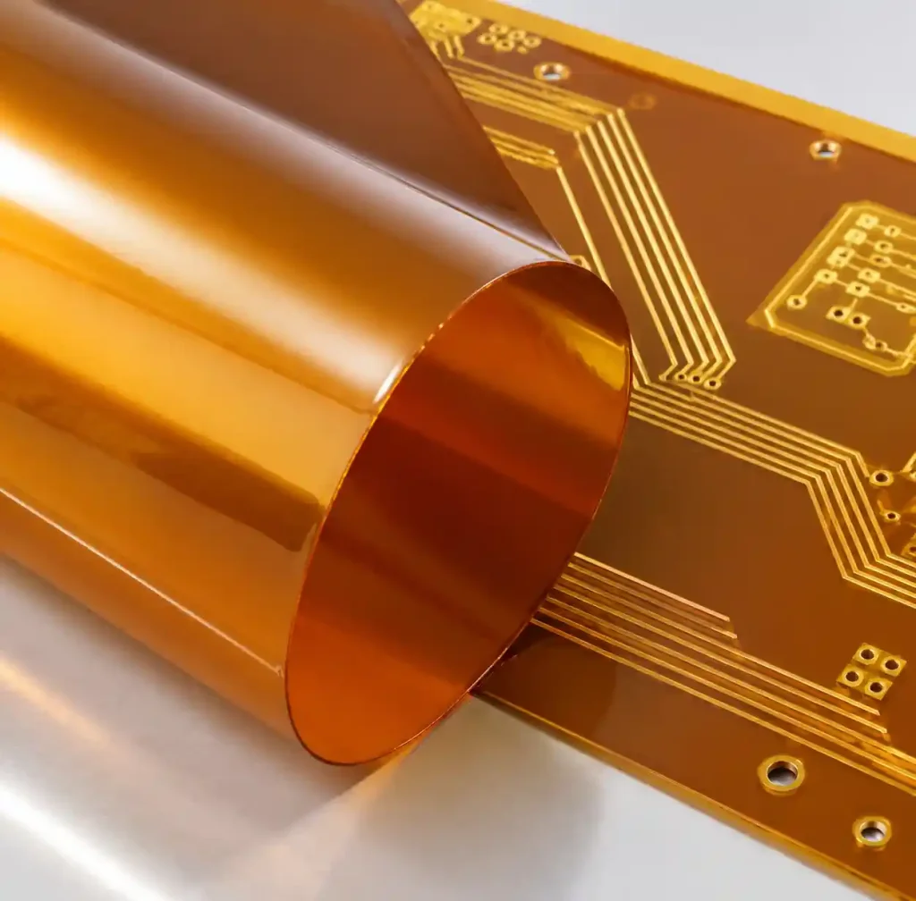
Standard FR-4 reaches glass transition temperature (Tg) around 130-140°C, insufficient for aerospace. High-Tg polyimide laminates maintain structural integrity to 250-280°C continuous operation. Materials like DuPont Kapton or Arlon 85N provide dimensional stability critical for multilayer registration when boards cycle between -55°C ground storage and +125°C cockpit environments.
Rogers high-frequency laminates (RO4003C, RO4350B) serve RF applications where dielectric constant stability matters. These ceramic-filled materials maintain Dk tolerance within ±2% across full aerospace temperature range, essential for phased array radar and satellite communication at X-band through Ka-band.
Low-Outgassing Materials for Space
Space-grade PCBs must pass NASA ASTM E595 outgassing tests: total mass loss (TML) below 1.0% and collected volatile condensable materials (CVCM) below 0.10% when heated to 125°C in vacuum. Standard epoxy resins and solder masks typically fail these requirements.
Qualified space materials include specialized PTFE-based laminates and modified epoxy systems. Every layer—base laminate, prepreg, solder mask, legend ink, and conformal coating—requires individual qualification with batch-specific outgassing test results.
| Material Type | Max Operating Temp | Tg Range | Typical Applications | Outgassing Qualified |
|---|---|---|---|---|
| High-Tg FR-4 | +130°C | 170-180°C | Avionics, flight control | No |
| Polyimide | +260°C | 250-280°C | Engine sensors, flex circuits | Yes (qualified grades) |
| Rogers RO4003C | +150°C | 280°C+ | Radar, satellite comm | Yes |
| PTFE (Teflon) | +260°C | N/A (no Tg) | Space RF, microwave | Yes |
Critical Testing and Qualification Requirements
Aerospace PCBs undergo validation testing beyond commercial standards, verifying design margin under worst-case environmental conditions over 15-20 year service life.
Thermal Cycling and Vibration
Temperature cycling per IPC-9701 requires minimum 500 cycles from -55°C to +125°C with 15-minute dwell times. Aerospace programs often specify 1000 cycles, stressing solder joints, plated through-holes, and material interfaces to verify no crack propagation occurs.
Avionics boards experience sustained vibration. Testing follows DO-160 environmental conditions, requiring swept frequency vibration from 10-2000 Hz at 20G acceleration. Boards must maintain electrical continuity with no solder joint failures or component detachment.
Electrical Testing and Microsection Analysis
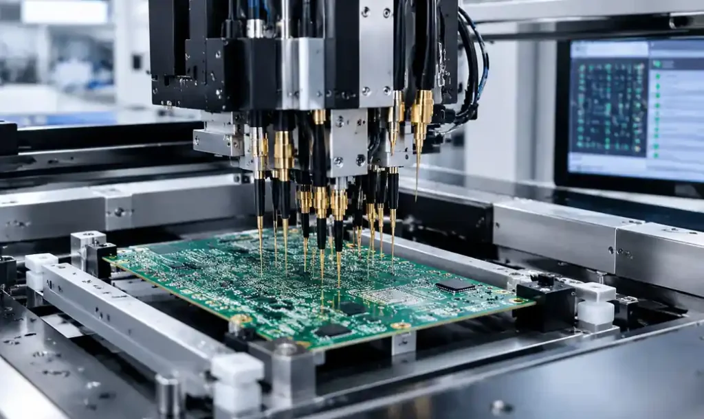
Every aerospace PCB undergoes 100% electrical testing. Automated equipment verifies net-to-net isolation exceeds 10MΩ and checks impedance on every controlled-impedance net (typically ±10% tolerance).
Microsection analysis of test coupons provides the final quality gate. Inspectors examine plating thickness in vias, verify minimum copper thickness at hole sidewalls, and measure resin recession. Any non-conformance to Class 3 criteria results in lot rejection.
ITAR Compliance for Defense Applications
Many aerospace PCBs fall under International Traffic in Arms Regulations (ITAR), particularly boards designed for military radar, avionics, missile guidance, or electronic warfare. Category XI specifically covers PCBs where layout is specially designed for defense articles.
ITAR compliance means controlling access to PCB design files and manufacturing data. Gerber files, assembly drawings, and test procedures constitute technical data that cannot be shared with foreign nationals without export licenses. Manufacturers must be ITAR-registered and maintain physical and electronic access controls.
Violations carry civil penalties up to $1,271,078 per incident. For commercial aerospace not involving defense systems, boards typically fall under Export Administration Regulations (EAR) rather than ITAR.
Design Considerations for Aerospace Reliability
Meeting AS9100 and IPC-6012 Class 3 starts with design choices giving manufacturers margin to meet specifications.
Via aspect ratios (board thickness divided by drill diameter) should not exceed 8:1 for standard through-holes, or 10:1 maximum. Higher ratios make achieving 25μm barrel plating difficult and increase drill wander risk.
Capture pad sizing must account for registration tolerances. For a 0.4mm drill, specify minimum 0.65mm finished pad diameter, providing 2.5 mil annular ring after accounting for ±3 mil registration and ±1 mil drill position tolerances.
Controlled impedance traces require ±10% tolerance (50Ω ±5Ω). Document target stackup with specific materials rather than generic “FR-4” callouts—aerospace manufacturers need exact dielectric constants to model impedance accurately.
Selecting an AS9100-Certified PCB Manufacturer
Not every PCB shop can fabricate aerospace boards. Look for manufacturers holding current AS9100 Rev D certification. The certificate scope must explicitly include PCB fabrication.
Evaluate Class 3 process capabilities. Request capability documentation showing minimum feature sizes, aspect ratio limits, and impedance control tolerance. Examine their document control system, calibration program, and handling procedures during facility audits.
Lead times for aerospace PCBs run 3-4 weeks typical versus 1-2 weeks for commercial boards. Additional time supports enhanced inspection, test coupon microsectioning, and documentation preparation.
FAQ
What is the difference between IPC Class 3 and Class 3A?
Class 3A is an addendum specifically for space and military avionics, adding requirements beyond Class 3 including enhanced thermal cycling (-55°C to +125°C minimum), additional via plating controls, stricter surface finish uniformity, and outgassing qualification. Class 3 suffices for commercial avionics; Class 3A applies for space environments or critical defense systems.
Do all aerospace PCBs require AS9100-certified manufacturers?
Most aerospace OEMs require AS9100 certification for direct suppliers. If designing PCBs for aircraft systems, avionics, or space applications, procurement specifications typically mandate AS9100-certified fabrication. For experimental aircraft or non-certified equipment, you might use non-AS9100 manufacturers, but you lose the traceability and process control aerospace quality systems provide.
How much do aerospace-grade PCBs cost compared to commercial boards?
Expect 2-3x cost premium for Class 3 aerospace PCBs versus equivalent Class 2 commercial boards. The increase reflects enhanced material costs (high-Tg laminates, low-outgassing materials), additional testing (microsection analysis, thermal cycling), tighter process control, and comprehensive documentation.
What temperature range must aerospace PCBs survive?
Standard aerospace qualification requires -55°C to +125°C operation per MIL-STD-810. This covers most cockpit avionics and external equipment. Engine-mounted sensors may require -55°C to +150°C. Space applications face wider extremes: LEO satellites cycle between -150°C (eclipse) and +150°C (sun) thousands of times during mission life.
Is ITAR compliance required for all aerospace PCBs?
No. ITAR applies only to PCBs specially designed for defense articles—typically military radar, avionics, missile systems, or military spacecraft. Commercial aircraft avionics, air traffic control systems, and commercial satellites generally fall under Export Administration Regulations (EAR). Your end customer’s program determines which export control regime applies.
Conclusion
Aerospace PCB requirements combine AS9100 quality management, IPC-6012 Class 3 manufacturing criteria, extreme-environment materials, comprehensive testing, and defense compliance. Success requires understanding these requirements during design phase—not as manufacturing afterthoughts.
Material selection drives reliability: high-Tg polyimide for thermal stability, Rogers laminates for RF performance, and space-qualified materials with verified outgassing data. Testing validates reliability through thermal cycling, vibration, and complete electrical verification backed by microsection analysis.
Selecting the right manufacturer matters as much as design. AS9100 certification demonstrates process maturity, but verify specific Class 3 capabilities and experience with your application. The 2-3x cost premium delivers the traceability and design margin aerospace applications demand.
For teams designing their first aerospace PCB, work with manufacturers holding current AS9100 certification and request early DFM review focused on Class 3 compliance. Investment in design-for-reliability reduces costly redesigns when programs reach qualification testing.
Sources: