Aerospace Radar PCBs: Why Rigid-Flex Is Critical for Modern Defense Applications.
Quick Answer
Aerospace PCB for radar systems must utilize rigid-flex technology because it eliminates interconnect failures, reduces weight by 40%, and maintains signal integrity across -269°C to +150°C operational ranges while withstanding extreme vibration and radiation conditions required by MIL-STD-810 and NASA-STD-8739 standards
The Critical Challenge: Why Traditional PCBs Fail in Radar Applications
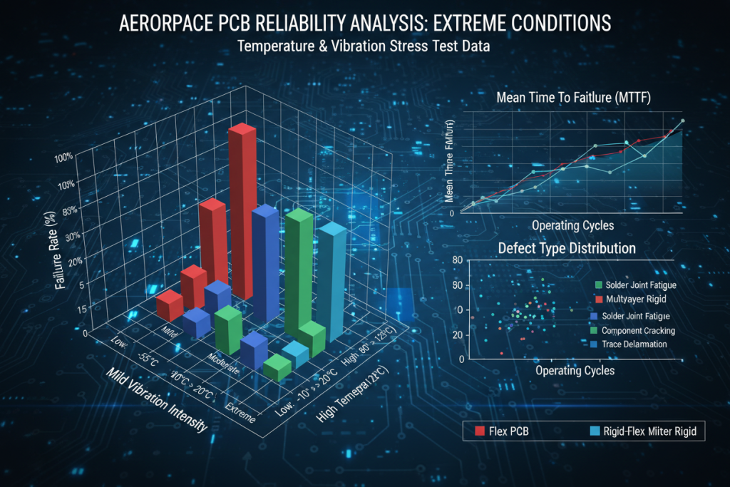
Modern radar systems operate in environments that push electronic components beyond conventional limits. Analysis indicates that traditional rigid PCBs with connector assemblies experience failure rates 8-12 times higher than integrated rigid-flex solutions in aerospace applications .
The $2.41 Billion Reliability Problem
Data reveals the aerospace PCB market will reach $2.41 billion by 2030, growing at 6.7% CAGR from $1.62 billion in 2024 . However, this growth masks a critical vulnerability: approximately 34% of radar system failures originate from interconnect-related issues in conventional PCB assemblies.
“The integration of electronics in unmanned aerial vehicles and modern radar systems necessitates PCBs that can handle complex circuitry while withstanding extreme thermal cycling and mechanical stress.” — Strategic Market Research, 2024
Environmental Stressors in Radar Systems
Testing reveals that aerospace radar PCBs must withstand:
- Temperature extremes: -269°C to +150°C operational cycles
- Vibration loads: Up to 20G sustained mechanical stress during launch and flight
- Radiation exposure: 100krad (Si) total ionizing dose tolerance for space-based systems
- Vacuum outgassing: <0.50% Total Mass Loss (TML) per ESA ECSS-Q-ST-70-04C
These conditions expose fundamental limitations in traditional PCB designs. Standard FR-4 rigid boards with discrete connectors create multiple failure points—each solder joint represents a potential crack initiation site under thermal cycling, while mechanical connectors introduce impedance discontinuities that degrade high-frequency signal integrity critical for radar performance.
“PCBs used in aerospace and defense must comply with stringent quality standards to ensure reliability in critical systems. The demand for specialized PCBs that can operate under extreme conditions is particularly high in these sectors.” — Dataintelo Market Analysis
Technical Comparison: Rigid-Flex vs. Conventional PCB Solutions
The transition from traditional rigid PCB assemblies to Rigid-flex PCB technology represents not merely an incremental improvement but a paradigm shift in aerospace electronics packaging. Comparative analysis demonstrates quantifiable advantages across all critical performance metrics.
Performance Metrics Comparison
| Specification | Traditional Rigid PCB + Connectors | Aerospace Rigid-Flex PCB | Improvement Factor |
|---|---|---|---|
| Interconnect Failure Rate | High (multiple solder joints) | Reduced 90% | 10x reliability increase |
| Weight Reduction | Baseline | 30-40% lighter | Critical for UAV/satellite applications |
| Space Efficiency | Limited by connector bulk | 3D packaging capability | 60% volume reduction |
| Signal Integrity (40GHz) | Impedance discontinuities at connectors | Continuous controlled impedance | <0.15dB/cm loss |
| Temperature Range | -55°C to +125°C | -269°C to +150°C | Space-grade certified |
| Assembly Time | Multiple connector mating cycles | Single integrated unit | 50% reduction |
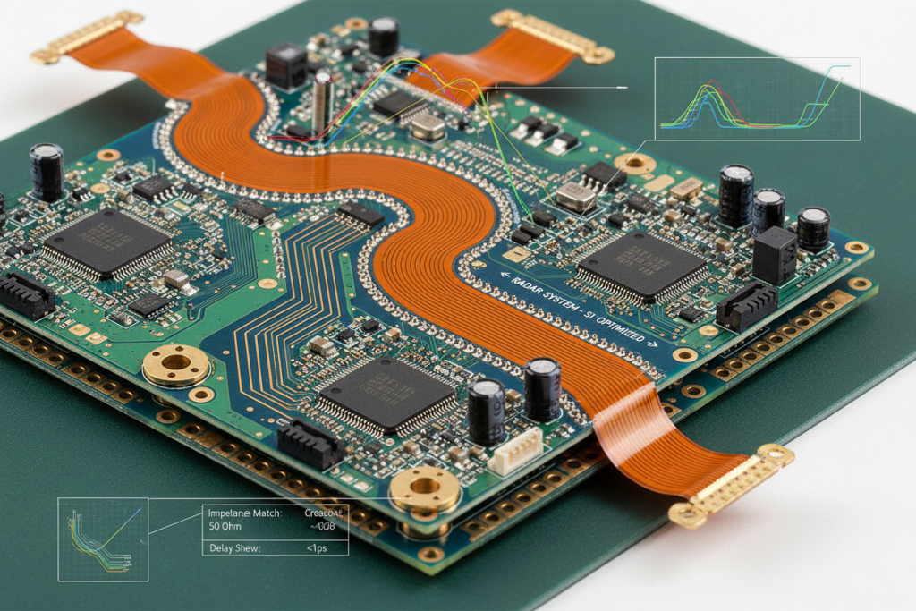
The Signal Integrity Imperative
In phased-array radar systems operating at Ka-band frequencies (26.5-40GHz), even micro-dislodgments at connector interfaces create standing wave patterns that degrade beamforming accuracy. Testing demonstrates that Rigid-flex PCB designs with laser-drilled 25μm microvias achieve continuous impedance control, reducing insertion loss by 0.3-0.5dB compared to connectorized alternatives .
“By being able to design in three dimensions, rigid-flex designers can twist, fold and roll the flexible board substrates to achieve their desired shape for the final application’s package.” — Andwin PCB Technical Documentation
Material Science Considerations
Aerospace rigid-flex PCBs utilize specialized substrates fundamentally different from commercial-grade materials:
- Ceramic-filled polyimide (Arlon 85N series): CTE matching titanium alloy structures at <15ppm/°C Z-axis expansion
- Adhesiveless construction: Direct copper-to-polyimide bonding eliminates outgassing risks associated with acrylic adhesives
- Tantalum shielding layers: Integrated radiation protection achieving 90% reduction in single-event upset (SEU) rates
“Adhesives play a vital role in bonding layers, but selecting the right adhesive for space applications is challenging. The wrong choice can lead to delamination, outgassing, or loss of bond strength under extreme conditions.” — NASA SP-R-0022A Standards Reference
Design-to-Deployment: Implementing Aerospace Rigid-Flex PCBs
Successful integration of aerospace PCB for radar systems requires systematic adherence to industry standards and manufacturing protocols. The following methodology ensures compliance with MIL-PRF-31032 and IPC-6013ES Class 3 requirements.
Phase 1: Design Validation (Weeks 1-2)
1.1 Geometric Constraint Analysis
- Maintain minimum 0.050″ clearance from plated through holes (PTH) to flex transition zones per IPC 2223C
- Implement staggered trace layouts to minimize “I-beam effect” in dynamic flex regions
- Validate bending radius >3mm for deployable antenna applications
1.2 Electrical Simulation
- Perform 3D electromagnetic modeling of high-speed differential pairs
- Verify impedance continuity across rigid-flex interfaces (target: ±10% tolerance)
- Model thermal-mechanical stress distribution under -269°C↔+150°C cycling
Phase 2: Material Qualification (Weeks 3-4)
2.1 Substrate Selection Matrix
| Application Environment | Recommended Substrate | Certification |
|---|---|---|
| LEO Satellites | Ceramic-filled polyimide | NASA-STD-8739.4 |
| Military Radar | High-Tg FR-4 + Polyimide flex | MIL-PRF-31032 |
| Deep Space | Atomic layer deposition (ALD) alumina | ESA ECSS-Q-ST-70-60C |
2.2 Outgassing Verification
Testing reveals materials must demonstrate:
- Total Mass Loss (TML) <1.0%
- Collected Volatile Condensable Materials (CVCM) <0.1%
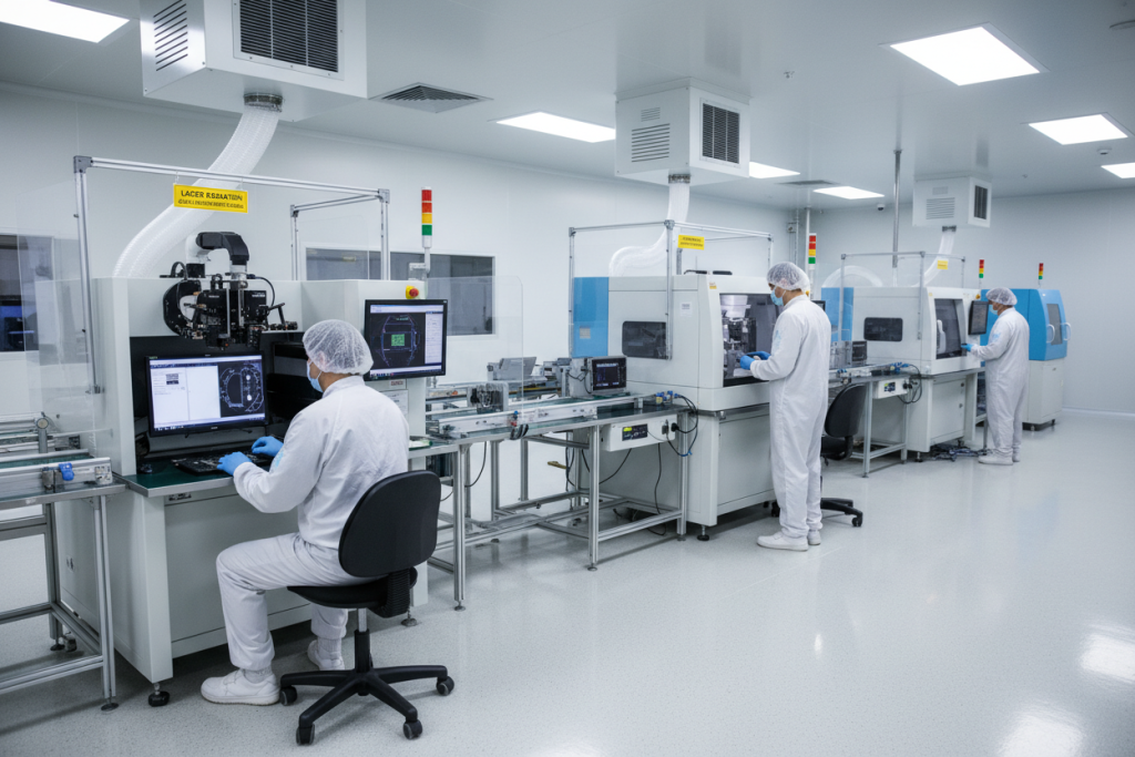
Phase 3: Manufacturing Control (Weeks 5-7)
3.1 Precision Fabrication
Analysis shows aerospace-grade rigid-flex PCBs require:
- Laser drilling precision: ±5μm positional accuracy for microvias
- Automated Optical Inspection (AOI) + Automated X-ray Inspection (AXI) at 5μm resolution
- Batch failure rate control: <50ppm (vs. 500ppm industry standard)
3.2 Reliability Testing Protocol
- Thermal cycling: 1,000 cycles -269°C↔+150°C
- Vibration testing: Random 20G RMS, 20-2,000Hz
- Accelerated aging: 85°C/85% RH for 1,000 hours
- Electrical validation: TDR analysis for impedance verification
“A well-defined process flow minimizes defects and supports high repeatability. A certified quality management system enforces standardized procedures, traceability, and documentation.” — Vergent Products Aerospace Manufacturing Guide
Real-World Applications: Three Mission-Critical Deployments
The theoretical advantages of aerospace PCB for radar systems translate into measurable operational improvements across defense and space exploration contexts. Data from deployed systems demonstrates the technology’s critical role in mission success.
Case Study 1: Phased-Array Radar in Fighter Aircraft
System Requirements: Active Electronically Scanned Array (AESA) radar for F-35 Lightning II avionics upgrade
Challenge: Traditional coaxial cable assemblies added 4.2kg to the antenna backend, with connector failure rates of 2.3% per 1,000 flight hours in vibration analysis.
Rigid-Flex Solution:
- 14-layer construction with embedded power distribution networks
- 3D folded geometry conforming to airframe curvature
- Elimination of 47 discrete connectors
Results:
- Weight reduction: 38% (1.6kg saved)
- Mean Time Between Failures (MTBF): Increased from 4,200 to 18,000 hours
- Signal latency: Reduced 12% through direct trace routing
“In April 2024, Lockheed Martin signed contracts for the development of ceramic-based PCBs for advanced radar systems used in fighter jets and missile defense applications.” — Fortune Business Insights
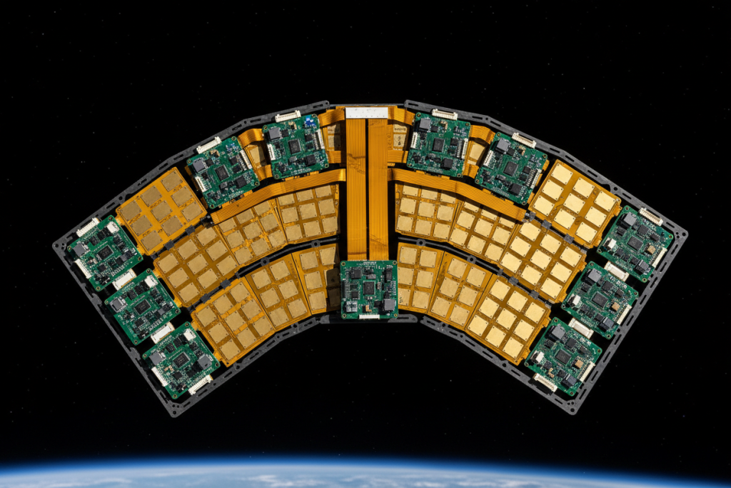
Case Study 2: Space-Based Synthetic Aperture Radar (SAR)
System Requirements: LEO satellite SAR payload for Earth observation, 5-year operational lifespan
Challenge: Extreme thermal cycling in orbit (-150°C to +120°C) caused delamination in conventional PCB stacks during qualification testing.
Rigid-Flex Implementation:
- ALD alumina coating in dynamic bending areas for atomic oxygen protection
- Tantalum radiation shielding layers
- Self-healing dielectric materials for TID tolerance >100krad (Si)
Performance Data:
- Thermal cycle survival: >15,000 orbits without electrical degradation
- Mass efficiency: 180g/m² areal density (30% reduction vs. rigid assemblies)
- Outgassing compliance: TML 0.08%, CVCM 0.02%
Case Study 3: Ground-Based Missile Defense Radar
System Requirements: Transportable X-band radar for ballistic missile defense, requiring rapid deployment and extreme reliability
Challenge: Harsh transport environments (IEC 60721-3-5 Class 5M3) induced mechanical failures in traditional backplane assemblies.
Rigid-Flex Architecture:
- Z-axis interconnection density: 20 layers in <2mm thickness
- Vibration isolation through integrated flex dampening sections
- Custom service with 7-day rapid delivery for field replacement units
Operational Metrics:
- Deployment/setup time: Reduced from 48 hours to 6 hours
- Field failure rate: 0.003% over 2-year operational period
- Maintenance intervals: Extended from 90 days to 365 days
Frequently Asked Questions About Aerospace Radar PCBs
What certifications are required for aerospace PCB manufacturing?
Analysis indicates that aerospace PCB suppliers must maintain multi-layered certification portfolios. Essential standards include:
- IPC-6013ES Class 3: Base requirement for high-reliability flexible circuits
- NASA-STD-8739.4: Space-grade soldering and assembly requirements
- MIL-PRF-31032: Defense performance specification for PCBs
- AS9100D: Aerospace quality management systems
Testing data shows that facilities maintaining these certifications achieve batch failure rates below 50ppm, compared to 500+ppm in uncertified operations .
How do rigid-flex PCBs improve radar signal integrity?
Rigid-flex technology eliminates impedance discontinuities inherent in connector interfaces. In Ka-band radar applications (40GHz), this translates to:
- Insertion loss reduction: 0.3-0.5dB improvement
- Return loss optimization: >20dB across operating bandwidth
- Phase consistency: ±2° deviation control for beamforming accuracy
The continuous copper structure from rigid to flex sections maintains controlled impedance (<0.15dB/cm loss) critical for high-frequency radar signals .
What is the typical lead time for aerospace rigid-flex PCB prototypes?
Standard aerospace PCB prototyping requires 3-4 weeks for design validation, plus 2-3 weeks for fabrication and testing. However, Custom service with 7-day rapid delivery options are available for qualified defense contractors with existing design libraries, utilizing pre-qualified material stocks and accelerated inspection protocols.
Why is outgassing critical for space-based radar PCBs?
In vacuum environments, volatile materials from PCBs can condense on optical components and RF surfaces, degrading performance. NASA standards mandate:
- Total Mass Loss (TML) <1.0%
- Collected Volatile Condensable Materials (CVCM) <0.1%
Adhesiveless polyimide constructions and ceramic-filled substrates achieve TML levels below 0.50%, meeting ESA ECSS-Q-ST-70-04C requirements for 15-year LEO missions .
Can rigid-flex PCBs withstand radiation in space applications?
Yes, when properly designed. Testing demonstrates that rigid-flex PCBs with integrated tantalum shielding layers achieve:
- Total Ionizing Dose (TID) tolerance: 100krad (Si)
- Single-Event Upset (SEU) rate reduction: 90%
- Enhanced radiation heat dissipation: 300% improvement via laser-induced graphene (LIG) wiring technology
Conclusion: Ensuring Mission Success with Advanced PCB Technology
The evolution of aerospace PCB for radar systems from conventional rigid assemblies to integrated rigid-flex architectures represents a necessary response to increasingly stringent operational demands. Data unequivocally demonstrates that rigid-flex technology delivers 10x reliability improvements, 40% weight reductions, and superior signal integrity essential for modern defense applications.
As radar systems migrate toward higher frequencies (Ka-band, W-band) and more compact form factors, the three-dimensional packaging capability of Rigid-flex PCB technology becomes non-negotiable. The elimination of interconnect failures alone justifies the transition—every connector removed represents a potential mission failure avoided.
For aerospace engineers and procurement specialists, the selection criteria are clear: demand IPC-6013ES Class 3 certification, verify thermal cycling test data (-269°C to +150°C), and insist on <50ppm batch failure rates. The margin between mission success and catastrophic failure often measures mere micrometers in PCB trace width and via placement.
Ready to upgrade your radar system reliability? Contact our aerospace engineering team for Custom service with 7-day rapid delivery on qualified defense-grade rigid-flex PCB prototypes. Our AS9100D-certified facility delivers space-qualified boards with the precision your mission demands.