
Skip to content
Andwin Circuits
  • Home
  • ProductsExpand
    • HDI multilayer PCB
    • Rigid Flex PCB
    • Flex pcb
    • Special PCBExpand
      • High Frequency PCBExpand
        • Rogers RO4350B PCB
        • Rogers RO4003 pcb
        • Rogers RO3003 PCB
        • Rogers 5880 PCB
        • DICLAD 527 PCB
        • Taconic TLX series
        • Taconic TLX-8 RF PCB
        • Taconic TLX-9 RF PCB
      • High speed pcbExpand
        • Megtron 6 High Speed PCB
        • TU-872 SLK Sp High Speed
      • High TG PCBExpand
        • SHENGYI SH260 PCB
        • ISOLA 370HR PCB
        • ISOLA IS410 PCB
        • ISOLA IS420 PCB
      • Heavy copper PCB
      • Copper coin pcb
      • Copper inlay PCB
    • Metal Core PCBExpand
      • Copper core pcb
      • Aluminum PCB
      • 2 Layers Aluminum PCB
      • Direct thermal MCPCB
      • 2 Layers Direct Thermal
    • Ceramic PCBExpand
      • DPC ceramic PCB
      • DBC ceramic PCB
      • Thick film Ceramic PCB
      • Al2O3 Alumina PCB
      • AIN ALN ceramic PCB
      • IGBT Ceramic PCB
  • ServiceExpand
    • PCB Assembly
    • Quick turn PCB assembly
    • PCBA conformal coating
  • IndustryExpand
    • Telecommunication
    • IoT and Wireless
    • Industrial Control
    • Thermal management
    • Power and Energy
    • IC test board
    • Automative
    • Medical
  • CapabilityExpand
    • Rigid PCB
    • Rigid flex PCB
    • Metal core PCB
    • PCB Assembly
  • TechnologyExpand
    • Blogs
    • Via in pad
    • PCB E-test
    • PCB stack up
    • MCPCB panelization
    • Controlled impedance PCB
  • AboutExpand
    • About us
    • Certification
    • Factory Tour
  • Contact
Andwin Circuits
Home / Common reasons for copper shedding in PCB factories

Common reasons for copper shedding in PCB factories

ByGrace February 25, 2025February 24, 2025

1.Laminate process reasons:

    Under normal circumstances, as long as the high temperature section of the laminate exceeds 30 minutes, the copper foil and the prepreg are basically completely combined, so the pressing generally does not affect the bonding strength between the copper foil and the substrate in the laminate. However, during the lamination and stacking process of the laminate, if the PP is contaminated or the rough surface of the copper foil is damaged, it will also lead to insufficient bonding between the copper foil and the substrate after lamination, resulting in positioning (only for large boards) or sporadic copper wire shedding, but there will be no abnormality in the copper foil peeling strength near the shedding line.

    2.Laminate raw material reasons:

    (1)It is mentioned above that ordinary electrolytic copper foil is a product that has been treated with galvanized or copper-plated raw foil.

    If the peak value of the raw foil is abnormal during production, or the coating crystal dendrites are poor during galvanizing/copper plating, the peeling strength of the copper foil itself is insufficient. After the poor foil is pressed into the PCB, the copper wire will fall off due to external force when it is plugged into the electronics factory. This type of poor copper shedding will not show obvious side etching after peeling off the copper wire to see the rough surface of the copper foil (i.e. the surface in contact with the substrate), but the peeling strength of the entire copper foil will be very poor.

    (2)Poor adaptability of copper foil and resin:

    Some laminates with special properties currently used, such as HTg sheets, are generally PN resins due to different resin systems. The resin molecular chain structure is simple and the degree of cross-linking is low during curing. It is necessary to use copper foil with a special peak value to match it. When copper foil is used in the production of laminates and does not match the resin system, the peeling strength of the metal foil on the sheet is insufficient, and poor copper wire shedding will occur during plug-in.
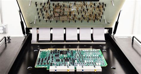
    Contact us for PCB quote now |

    3.PCB factory process factors:

    (1)Excessive etching of copper foil.

    The electrolytic copper foil used in the market is generally single-sided galvanized (commonly known as gray foil) and single-sided copper (commonly known as red foil). Common copper shedding is generally galvanized copper foil above 70um. Red foil and gray foil below 18um have basically not experienced batch copper shedding.

    When the customer’s circuit design is done and the etching line is done, if the copper foil specifications are changed but the etching parameters remain unchanged, the copper foil will stay in the etching solution for too long.

    Because zinc is originally an active metal, when the copper wire on the PCB is immersed in the etching solution for a long time, it will inevitably lead to excessive side etching of the circuit, causing the zinc layer on the back of some thin circuits to be completely reacted and separated from the substrate, that is, the copper wire falls off. There is also a situation where there is no problem with the PCB etching parameters, but the washing and drying after etching are poor, causing the copper wire to be surrounded by the etching solution remaining on the PCB surface.

    If it is not treated for a long time, it will also cause excessive side etching of the copper wire and copper shedding. This situation is generally manifested as concentrated on thin circuits, or in humid weather, similar defects will appear on the entire PCB. When the copper wire is peeled off, the color of the contact surface with the base layer (the so-called roughened surface) has changed, which is different from the normal copper foil color. The color of the original copper on the bottom layer is seen, and the peeling strength of the copper foil at the thick circuit is also normal.
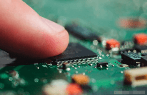
    Contact us for PCB quote now |

    (2)A local collision occurs during the PCB process, and the copper wire is separated from the substrate by external mechanical force. This defect is manifested as poor positioning or directionality. The detached copper wire will be obviously twisted, or there will be scratches/impact marks in the same direction. Peel off the copper wire at the defective part and look at the rough surface of the copper foil. You can see that the rough surface of the copper foil has normal color, there will be no side corrosion, and the peeling strength of the copper foil is normal.

    (3)The PCB circuit design is unreasonable. Using thick copper foil to design too thin circuits will also cause excessive circuit etching and copper shedding.

    Contact us for PCB quote now |
      Post Tags: #aluminum clad pcb#aluminum core pcb#aluminum core pcb led#aluminum pcb#assemble pcb

      Post navigation

      Previous Previous
      Key Factors in Partnering With Trusted PCB Assembly Manufacturers
      NextContinue
      Methods to judge the quality of PCB circuit boards

      Search

      Search

      Products

      • HDI Multilayer PCB
      • Rigid Flex PCB
      • Flex pcb
      • High Frequency PCB
      • High speed pcb
      • Heavy copper PCB
      • Metal Core PCB
      • Ceramic PCB

      Address

      Andwin Circuits Co.,Limited
      Email: sales@andwinpcb.com
      Tel: +86 755 2832 9394
      Fax:+86 755 2992  6717
      ADD:1-2F-1217,HouDeQun Industrial park,
      NanTing RD NO.56,ShaJing,BaoAn,Shenzhen 518104,GuangDong,China

      Products

      • HDI Multilayer PCB
      • Rigid Flex PCB
      • Flex pcb
      • High Frequency PCB
      • High speed pcb
      • Heavy copper PCB
      • Metal Core PCB
      • Ceramic PCB

      Technology

      • Blogs
      • Via in pad
      • PCB E-test
      • PCB stack up
      • Metal core PCB panelization
      • Controlled impedance PCB

      CERTIFICATION

      Certification >>


      Copyright© 2003 - 2026 Andwin | All Rights Reserved | Powered by Andwin

      Scroll to top
      • Home
      • Products
        • HDI multilayer PCB
        • Rigid Flex PCB
        • Flex pcb
        • Special PCB
          • High Frequency PCB
            • Rogers RO4350B PCB
            • Rogers RO4003 pcb
            • Rogers RO3003 PCB
            • Rogers 5880 PCB
            • DICLAD 527 PCB
            • Taconic TLX series
            • Taconic TLX-8 RF PCB
            • Taconic TLX-9 RF PCB
          • High speed pcb
            • Megtron 6 High Speed PCB
            • TU-872 SLK Sp High Speed
          • High TG PCB
            • SHENGYI SH260 PCB
            • ISOLA 370HR PCB
            • ISOLA IS410 PCB
            • ISOLA IS420 PCB
          • Heavy copper PCB
          • Copper coin pcb
          • Copper inlay PCB
        • Metal Core PCB
          • Copper core pcb
          • Aluminum PCB
          • 2 Layers Aluminum PCB
          • Direct thermal MCPCB
          • 2 Layers Direct Thermal
        • Ceramic PCB
          • DPC ceramic PCB
          • DBC ceramic PCB
          • Thick film Ceramic PCB
          • Al2O3 Alumina PCB
          • AIN ALN ceramic PCB
          • IGBT Ceramic PCB
      • Service
        • PCB Assembly
        • Quick turn PCB assembly
        • PCBA conformal coating
      • Industry
        • Telecommunication
        • IoT and Wireless
        • Industrial Control
        • Thermal management
        • Power and Energy
        • IC test board
        • Automative
        • Medical
      • Capability
        • Rigid PCB
        • Rigid flex PCB
        • Metal core PCB
        • PCB Assembly
      • Technology
        • Blogs
        • Via in pad
        • PCB E-test
        • PCB stack up
        • MCPCB panelization
        • Controlled impedance PCB
      • About
        • About us
        • Certification
        • Factory Tour
      • Contact
      Search