
Differential lines
Differential lines are a very important part of signal lines in PCB design, and the signal processing requirements are also quite strict. Today, I will introduce the principle of differential signals and their processing methods in PCB design.
1.What is differential signal
Differential transmission is a signal transmission technology. Different from the traditional method of one signal line and one ground line, differential transmission transmits signals on both lines. The amplitudes of the two signals are equal, the phase difference is 180 degrees, and the polarity is opposite. The signal transmitted on these two lines is a differential signal.
2.The difference between differential signals and single-ended signals
Single-ended signals refer to signals transmitted by one line.
How can there be a signal without a reference point on a line? The reference point is the ground. In other words, a single-ended signal is the level difference between the ground and the signal transmitted on a wire. So when you transmit the signal from point A to point B, there is a premise that the ground potential of points A and B should be almost the same.
3.Differential signals refer to signals transmitted by two lines, and what is transmitted is the level difference between the two signals.
When you pass a signal from point A to point B, the ground potentials at point A and point B can be the same or different, but there is a range of ground potential differences between points A and B before problems arise.
A differential signal is a signal that represents the difference between two physical quantities using a single value. Strictly speaking, all voltage signals are differential because one voltage can only be measured relative to another voltage. In some systems, the system ground is used as a voltage reference. When ground is used as a voltage reference, the signal arrangement is called single-ended. We use this term because the signal is represented by the voltage on a single conductor.
A differential signal, on the other hand, acts on two conductors.
The signal value is the difference in voltage between the two conductors. The average of the two voltages will often be the same, although not necessarily. A way to compare a differential signal is to think of it as two people on a seesaw. When one person is pushed up, the other person is pushed down – but their average position remains the same. Continuing with the seesaw analogy, a positive value would mean that the person on the left is higher than the person on the right, while a negative value would mean that the person on the right is higher than the person on the left. 0 means that both people are at the same level. The two seesaws are represented by a pair of wires marked V+ and V-. When V+>V-, the signal is defined as a positive signal, and when V+
3. Advantages of differential signals
Advantage 1. Compared with single-ended signals, differential signals reduce potential electromagnetic interference (EMI). Using differential transmission, the peak-to-peak voltage of the signal will be doubled, but the current on a single line remains unchanged. If the traditional single-wire transmission method is used, it is more likely to cause EMI problems when driving the same signal.
Advantage 2. The value of the differential signal is largely independent of the precise value of the “ground” and can resist power supply interference very well.
In a system with a ground reference and a single-ended signal solution, the precise value of the measured signal depends on the consistency within the system.
The farther the signal source and the signal receiver are, the greater the possibility of differences between their local ground voltage values. The signal value recovered from the differential signal is largely independent of the precise value of the ground, but within a certain range.
If both signals receive the same (same direction, equal amplitude) interference signal, the interference signal will be basically canceled out because the receiving end performs subtraction processing on the two received line signals. In other words, the input effective signal amplitude of a differential amplifier only needs a few millivolts, but it can be indifferent to a common-mode signal of up to several volts.
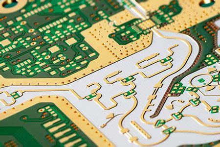
Advantage three, each signal in the differential pair has its own return path, which can reduce the impact of signal cross-splitting.
The single-line cross-splitting has a great impact on the transmission line, while the differential line pair cross-splitting is not so sensitive. The main reason is that the two lines of the differential pair can refer to each other, and the two lines can serve as return paths for each other. Fourth, the processing method of differential signals when doing PCB design
Generally, when we do PCB design, we usually add “+” and “-” or “P” and “N” to the end of the signal name of the differential signal as an identifier in the hardware naming. You can identify the differential signal by naming. Conventional differential signal processing methods are:
- The differential signal routing needs to be coupled, that is, the two signal lines are close together during PCB design, and separate routing is not allowed.
- The two signal lines of a pair of differential signals need to be equal-length processed, and the equal-length range is 5mil. The equal length does not need to be smaller. There is simulation verification that the equal length range is less than 5mil (1mil) and does not greatly improve the signal quality. The location of the equal length processing is selected where the length error occurs, and the equal length needs to be processed with a small wave.