
EMC research on RF circuits and antennas
When RF circuits are designed according to a pre-set scheme, their performance may not be fully up to standard. An important factor that causes RF performance to fail to meet standards may be electromagnetic interference. Electromagnetic interference is not necessarily caused by unreasonable circuit layout and wiring in the RF field, but may also be caused by other aspects. In most cases, interference only occurs when combined with other circuits, such as digital circuits, power supply circuits, etc.
Dealing with interference problems is a compulsory course for design work, and it is also one of the focuses of RF design and preliminary research work. Here we briefly talk about the understanding and recognition of electromagnetic interference in RF.
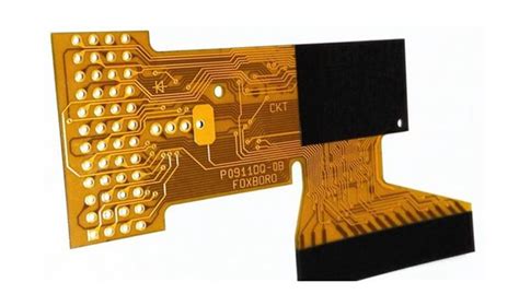
Electromagnetic interference (EMI) is ubiquitous in electronic systems and equipment, but it is particularly prominent in the RF field.
Although electromagnetic interference has various manifestations in RF systems, the most prominent and significant impact should be the impact of the sensitivity of the key pointer of the low-noise amplification of the front-end of the RF system. The second is the visible and audible impact of video and audio signals, etc., which is also what we are most concerned about when doing RF work. Where does the interference come from? Is it the low noise of the RF hardware itself, the system is not done well, or the antenna is not done well?
If we firmly believe that there is no problem with low noise, system, antenna, etc., our minds will involuntarily think of interference: Is the interference signal affecting the RF performance? In most cases, if you are not a senior technician, to consider the EMI interference level, you usually have to toss back and forth on the RF low noise amplifier, system, and antenna for several rounds, and even waste a lot of time, and finally consider the interference level. Products with no interference and good performance are all happy; products with interference have different effects depending on their functions. Considering interference issues has become our most important agenda.
When considering interference, we may ask: What is interference, where does the interference come from, how to test and quantify interference? The important thing is how to reduce interference? EMC problems are unexpected. In our long-term work, we have also had unforgettable experiences that have been deeply affected by electromagnetic interference. Therefore, in our long-term work, we continue to summarize, analyze, and explore EMC-related problem handling techniques and skills, which have now become our most valuable experience. After countless verifications, dealing with interference problems is generally easy.
Electromagnetic interference (EMI) is ubiquitous in electronic systems and devices, so how to make electronic systems and devices meet the requirements of electromagnetic compatibility (EMC) is a key technology.
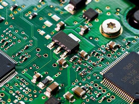
Due to the rapid development of RF and microwave fields, high demand has prompted RF engineers to pay more and more attention to RF circuit design skills.
The design of RF circuit boards is the most troublesome part for design engineers. If you want to succeed at one time, careful planning and attention to details are two key design rules that must be highly valued. And in all PCB designs, it is an important design rule to keep digital circuits as far away from analog circuits as possible. Otherwise, design changes caused by negligence in this regard may cause an almost completed design to be torn down and re-started. The serious consequences of this negligence will be self-evident.
Because RF circuit board PCB design still has many uncertainties in theory, it is often described as a kind of black magic, but this view is only partially correct. There are also many rules that can be followed and rules that should not be ignored in RF circuit PCB design. However, in actual design, the real practical skills are how to compromise when these rules and regulations cannot be accurately implemented due to various design constraints.
Today’s RF circuit designs mostly integrate everything in various ways, which is not good for RF circuit board PCB design.
The industry is very competitive now, and people are looking for ways to integrate the most functions in the smallest size and lowest cost. Analog, digital, and RF circuits are all tightly packed together, leaving little room to separate their respective problem areas, and the number of circuit board layers is often minimized for cost reasons. It is incredible that multi-purpose chips can integrate multiple functions on a very small chip, and the pins connecting to the outside world are arranged very closely, so RF, IF, analog, and digital signals are very close, but they are usually electrically unrelated. Power distribution can be a nightmare for designers. In order to extend battery life,