
Flex PCB Applications: From Wearables to Aerospace
Flexible printed circuit boards account for 25% of global PCB production value, reaching $23.89 billion in 2024 with 13.7% annual growth through 2030. Flex PCB adoption is driven by miniaturization requirements and reliability demands that rigid boards cannot meet.
This guide covers flex PCB applications across consumer electronics, medical devices, automotive systems, aerospace equipment, and industrial automation.
What Are Flex PCB Applications?
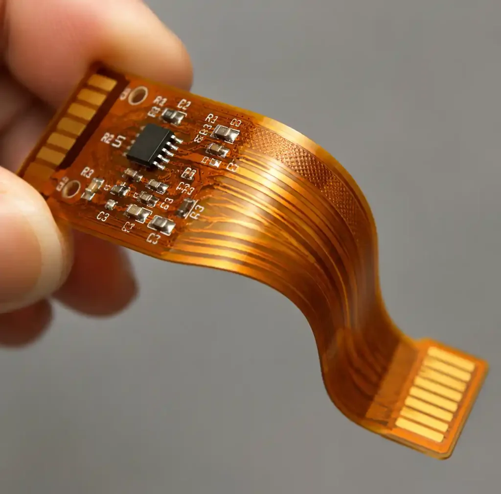
Flex PCB applications refer to electronic systems using flexible printed circuit boards manufactured on polyimide substrates that bend, fold, and twist without losing connectivity.
You can replace rigid boards with connectors and cables, reducing assembly complexity by 60-70% while improving reliability. The technology enables three-dimensional packaging for curved surfaces and tight spaces.
Consumer Electronics and Wearable Applications
Smartwatches and Fitness Trackers
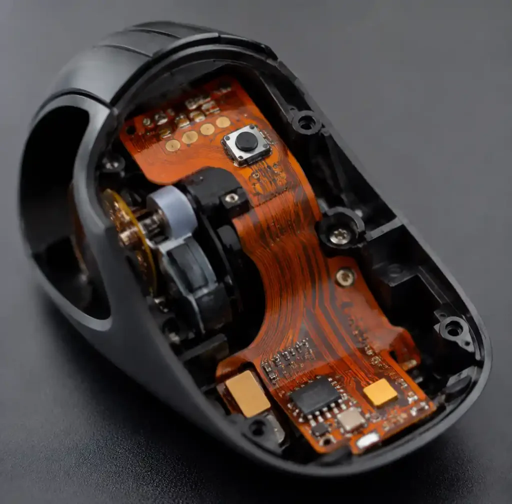
The wearable technology market will exceed $180 billion by 2026, with flex PCBs in every smartwatch and fitness tracker. These devices require circuits conforming to curved wrists while surviving millions of flex cycles.
Flex PCBs enable 30-40% smaller device thickness compared to rigid boards with connectors. High-density interconnect (HDI) flex technology supports component densities exceeding 200 devices per square inch. Modern fitness trackers use flex circuits rated for 100,000+ flex cycles at 5mm bend radius.
Smartphones and Tablets
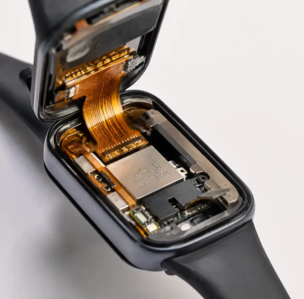
Smartphone manufacturers rely on flex PCB for camera modules, display connections, and battery interfaces. Flex circuits must meet IPC-6013 Class 2 standards and support impedance-controlled routing at 90Ω ±10% for MIPI DSI interfaces. Foldable phone designs require display PCBs bending 200,000+ times at 4mm radius without conductor fracture.
Medical Device Applications
Implantable Cardiac Devices
Pacemakers and implantable cardioverter defibrillators use rigid flex PCB constructions operating continuously for 7-15 years inside the human body. These assemblies require biocompatible polyimide substrates compliant with ISO 10993 biocompatibility standards and IPC Class 3 manufacturing quality.
You should specify dual-trace power routing with independent ground planes to prevent single-point failures in life-critical systems. The boards must resist body fluids, withstand steam sterilization at 134°C, and maintain signal integrity under cardiac motion stress.
| Medical Application | Flex Type | Layer Count | Key Requirement | Operating Life |
|---|---|---|---|---|
| Pacemaker | Rigid-Flex | 4-8 layers | ISO 10993 biocompatibility | 7-15 years |
| Hearing Aid | HDI Flex | 2-4 layers | <0.2mm thickness | 3-5 years |
| Glucose Monitor | Single-sided Flex | 1-2 layers | Skin-safe adhesive | 14 days |
| Endoscope Camera | Rigid-Flex | 4-6 layers | Autoclave resistant | 1000+ cycles |
Hearing Aids and Cochlear Implants
Hearing aids leverage HDI flex PCBs to achieve extreme miniaturization in devices smaller than a fingertip. These circuits use 01005 component sizes (0.4mm × 0.2mm) and up to 6 layers to pack digital signal processors, microphones, and wireless transceivers into sub-cubic-centimeter volumes.
Liquid crystal polymer (LCP) substrates provide flexibility with low moisture absorption, maintaining dimensional stability in humid ear canal environments better than standard polyimide.
Automotive and Electric Vehicle Applications
Dashboard and Sensor Systems
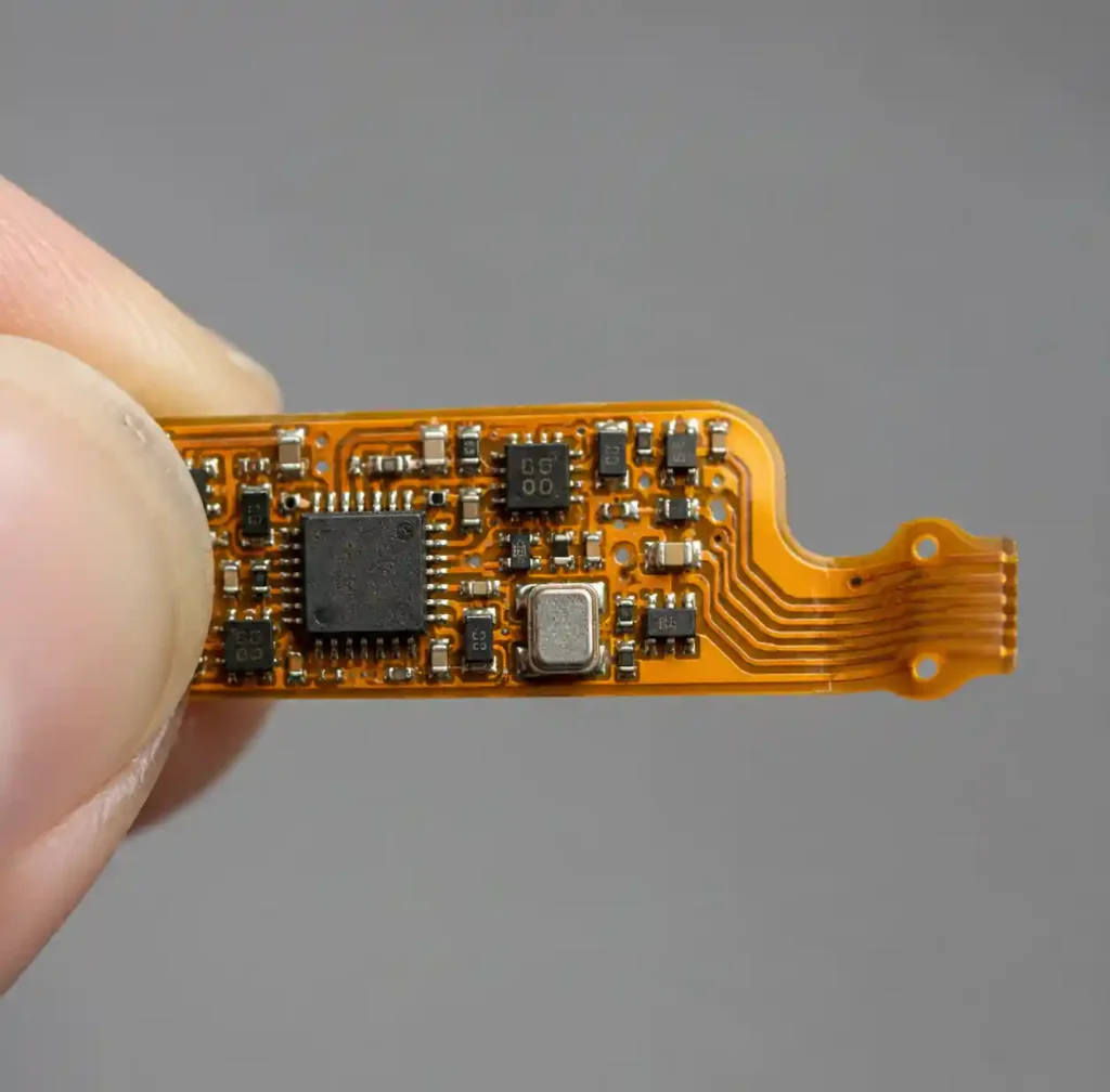
Automotive flex PCBs route signals from accelerometers, proximity detectors, and camera modules in constrained dashboard assemblies. These circuits must meet AEC-Q200 qualification standards and operate across -40°C to +125°C temperature ranges per IATF 16949 requirements.
Autonomous vehicle sensor systems use flex PCBs for cameras, radar, and LiDAR in compact housings, providing impedance-controlled routing at 100Ω differential for Ethernet camera links.
Battery Management Systems
Electric vehicle battery management systems deploy flex PCBs to monitor and control individual cell voltages across battery packs containing 200-400 cells. These circuits withstand vibration levels up to 20G per IEC 60068-2-64 standards while maintaining ±0.1% voltage measurement accuracy.
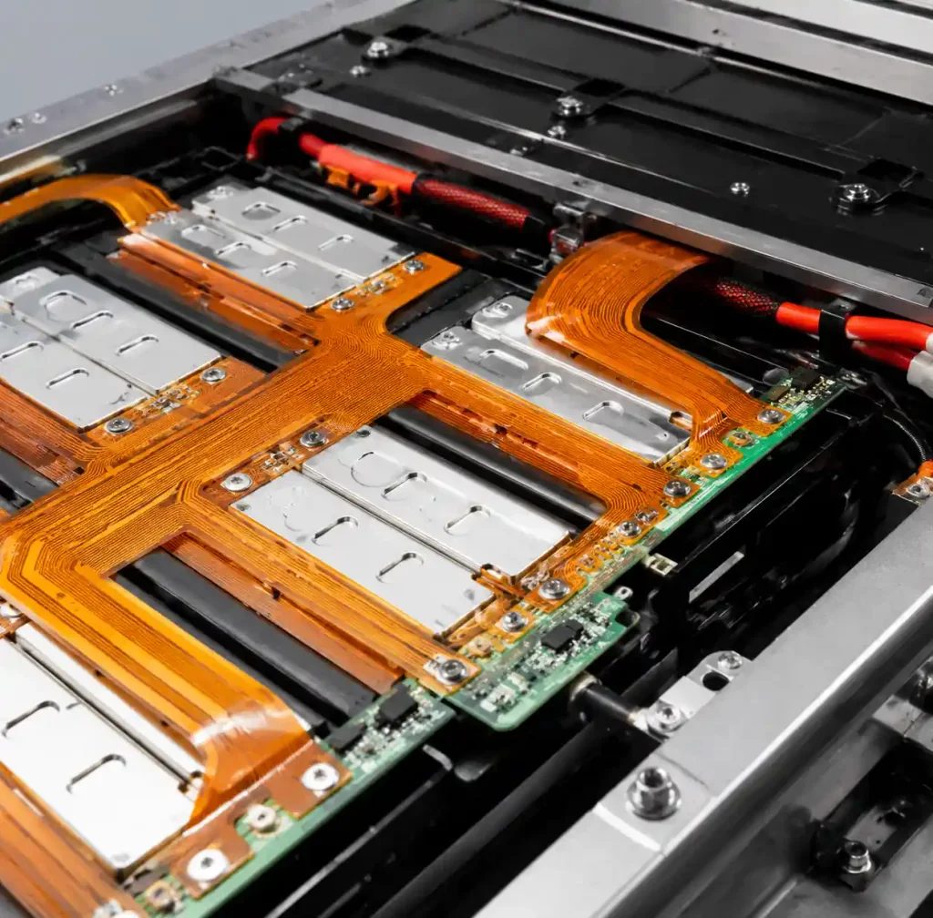
EV battery flex circuits require 2oz copper weight (70μm) for current-carrying capacity and polyimide substrates rated to Tg 260°C for thermal stability. The flex sections must survive 10,000+ flexing cycles at 10mm radius during battery pack assembly and service life.
| Automotive Application | Flex Configuration | Copper Weight | Temperature Range | Standard |
|---|---|---|---|---|
| Dashboard Display | 2-layer flex | 0.5oz (17μm) | -40°C to +85°C | AEC-Q200 |
| Battery Management | 4-layer flex | 2oz (70μm) | -40°C to +125°C | IATF 16949 |
| ADAS Camera | Rigid-flex | 1oz (35μm) | -40°C to +105°C | ISO 26262 |
| LED Lighting | 2-layer MCPCB flex | 3oz (105μm) | -40°C to +150°C | AEC-Q200 |
Aerospace and Satellite Applications
Satellite Systems
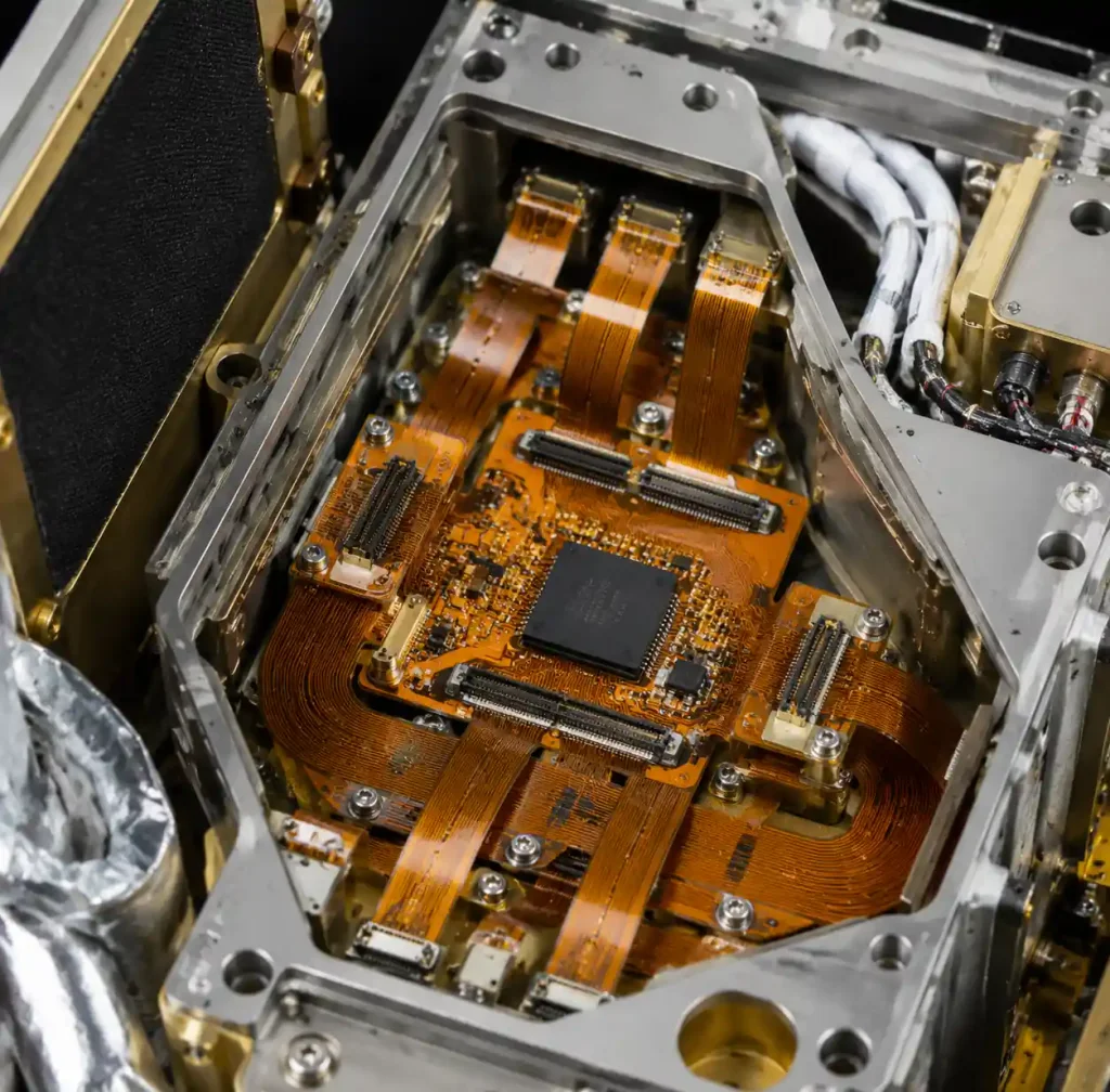
Satellites use flex PCBs extensively because they conform to tight spaces where weight and volume are critical constraints. The thin film construction saves 40-60% volume compared to rigid substrates.
Space-qualified flex circuits must withstand launch vibration exceeding 30G, survive thermal cycling between -180°C and +150°C, and operate in high-radiation environments for 10-15 year mission durations. You should specify polyimide substrates with IPC-6013 Class 3 qualification and gold-plated surfaces to prevent tin whisker formation in vacuum.
Avionics and Radar Systems
Aerospace radar systems use rigid flex PCB technology combining flexible interconnects with rigid mounting sections. Traditional rigid PCBs with connectors experience failure rates 8-12 times higher than integrated rigid-flex solutions due to vibration-induced connector loosening.
Avionics flex circuits require controlled impedance routing at 50Ω ±5% for RF signals up to 18 GHz. The boards must meet DO-160G environmental qualification including lightning strike protection per section 22 requirements.
Industrial Robotics and Automation
Robotic Arms and Moving Joints
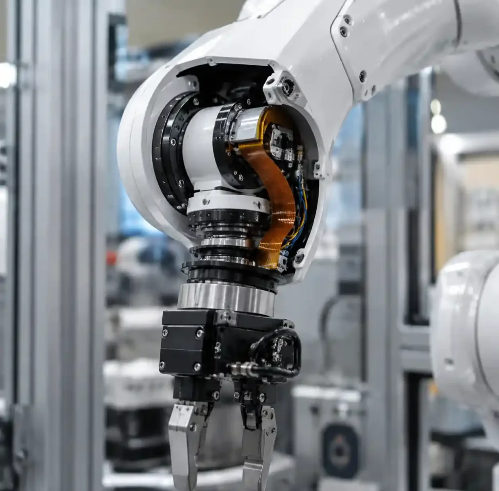
Industrial robots deploy continuous-flex cable assemblies rated for 10-30 million flex cycles in robotic arms, rotating joints, and gripper mechanisms. These circuits route power, motor control signals, encoder feedback, and Ethernet communication through moving mechanical assemblies.
Rolled-annealed copper conductors provide 3-5 times longer flex life compared to standard electrodeposited copper. High-flex robotics applications require dynamic bend radii as small as 5-10× the cable thickness while maintaining signal integrity for EtherCAT industrial Ethernet running at 100 Mbps.
Factory Automation Systems
Factory automation systems use flex PCBs in conveyor controls, sensor networks, and pick-and-place machines that operate continuously under vibration and temperature swings. These circuits eliminate traditional wire harnesses that require frequent maintenance.
Flex circuits in industrial environments must meet IP67 ingress protection when integrated into sealed assemblies. Design these boards with stiffeners at connector areas and conformal coating rated to IPC-CC-830 Class 3 for chemical and moisture resistance.
Flex PCB Design Considerations by Application
Bend Cycle Requirements
Different applications require vastly different flex cycle capabilities. Consumer wearables need 100,000-500,000 cycles, medical devices require 1-10 million cycles, and industrial robots demand 10-30 million cycles for continuous flexing.
Higher flex life requires rolled-annealed copper, bend radius 10× or greater than material thickness, and traces perpendicular to bend axis. Avoid vias in flex regions as they reduce fatigue life by 80-90%.
Environmental and Reliability Standards
Aerospace applications must meet IPC-6013 Class 3 standards with enhanced reliability requirements. Automotive systems require IATF 16949 certification and AEC-Q200 component qualification. Medical devices need ISO 13485 quality systems and ISO 10993 biocompatibility validation.
| Industry | Key Standard | Reliability Test | Temperature Range | Expected Life |
|---|---|---|---|---|
| Consumer Electronics | IPC-6013 Class 2 | 1000 hrs @ 85°C/85% RH | -20°C to +70°C | 3-5 years |
| Medical Devices | IPC-6013 Class 3 | Accelerated aging per ASTM F1980 | -10°C to +50°C | 7-15 years |
| Automotive | IATF 16949 | 1000 hrs @ 150°C + vibration | -40°C to +125°C | 15 years |
| Aerospace | IPC-6013 Class 3 | Thermal cycling -180°C to +150°C | -180°C to +150°C | 10-20 years |
| Industrial | IPC-6013 Class 2 | IP67 ingress + chemical exposure | -25°C to +85°C | 10 years |
Material Selection Guidelines
Polyimide remains the dominant flex substrate material with Tg ratings from 250°C to 410°C depending on grade. Specify high-Tg polyimide (Tg >360°C) for aerospace and automotive applications requiring enhanced thermal performance.
Liquid crystal polymer (LCP) substrates offer superior moisture resistance and dimensional stability. LCP maintains <0.02% water absorption versus 2-3% for polyimide, making it ideal for medical implantables and high-frequency RF applications above 10 GHz.
Frequently Asked Questions
What is the difference between flex PCB and rigid-flex PCB?
Flex PCB consists entirely of flexible substrate materials that can bend throughout their length. Rigid-flex PCB combines rigid board sections for component mounting with flexible interconnect sections. Choose flex PCB for simple interconnect applications and rigid-flex for complex assemblies requiring both mounting stability and flexible routing.
How many flex cycles can flex PCBs withstand?
Flex cycle capability ranges from 100,000 cycles for consumer electronics to 30 million cycles for industrial robotics. Static flex applications where the circuit bends once during assembly can achieve unlimited life. Dynamic flexing life depends on bend radius, copper type, trace orientation, and flexing speed.
Are flex PCBs suitable for high-temperature applications?
Yes, flex PCBs operate reliably in high-temperature environments when designed with appropriate materials. Standard polyimide substrates support continuous operation up to 150°C and excursions to 260°C during PCB assembly. High-temperature polyimide grades rated to Tg 360-410°C enable aerospace and automotive applications up to 200°C continuous operation.
What industries use flex PCBs most?
Consumer electronics accounts for 45% of flex PCB demand, followed by automotive (25%), medical devices (12%), aerospace (8%), and industrial applications (10%). The wearable device market drives significant growth with products requiring extreme miniaturization.
Can flex PCBs replace traditional wire harnesses?
Yes, flex PCBs effectively replace wire harnesses in applications requiring weight reduction, space savings, and improved reliability. Flex circuits eliminate individual wire terminations that contribute to 70-80% of harness failures. You can achieve 50-60% weight savings and 40-50% volume reduction compared to equivalent wire harnesses.
Conclusion
Flex PCB technology enables modern electronic products across consumer, medical, automotive, aerospace, and industrial sectors. Understanding application-specific requirements for bend cycles, environmental conditions, and reliability standards helps you select the optimal flex circuit configuration.
If you need high-quality flex PCB or rigid flex PCB for your electronic device project, Andwin Circuits offers advanced manufacturing capabilities up to 50 layers with fast turnaround in 7 days. Our facility maintains ISO 9001, IATF 16949, and UL certifications for automotive, medical, telecommunications, and aerospace applications worldwide.
Contact us today for custom flex PCB solutions, technical specifications, and competitive factory-direct pricing.