
Flexible PCB Resistance: Key Factors, Measurement, and Optimization
Abstract
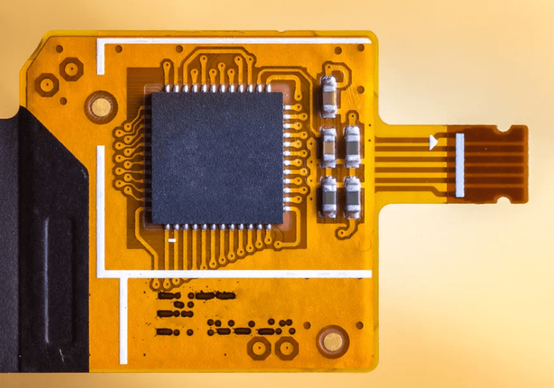
Flexible printed circuit boards (Flex PCBs) are widely used in modern electronics due to their lightweight, bendability, and space-saving advantages. However, their electrical resistance is a critical parameter that affects performance, especially in high-frequency and high-power applications. This article explores the factors influencing Flex PCB resistance, measurement techniques, and optimization strategies to ensure reliability and efficiency.
1. Introduction
Flex PCBs are essential in applications such as wearable devices, medical implants, aerospace systems, and consumer electronics. Unlike rigid PCBs, their flexible nature introduces unique challenges in maintaining consistent electrical resistance under mechanical stress, temperature variations, and environmental conditions. Understanding and controlling resistance in Flex PCBs is crucial for signal integrity, power delivery, and overall circuit performance.

2. Factors Affecting Flex PCB Resistance
2.1 Conductor Material
The choice of conductor material significantly impacts resistance. Common materials include:
- Copper (Cu): Most widely used due to its excellent conductivity (~1.68 µΩ·cm).
- Silver (Ag): Lower resistance but higher cost.
- Gold (Au): Used for high-reliability applications but expensive.
- Conductive Inks: Used in printed electronics but have higher resistance.
2.2 Trace Geometry
- Width and Thickness: Wider and thicker traces reduce resistance.
- Length: Longer traces increase resistance linearly (R = ρL/A, where ρ is resistivity, L is length, and A is cross-sectional area).
2.3 Substrate and Dielectric Properties
Flex PCBs use polyimide or PET substrates, which are non-conductive but influence impedance and signal loss. Dielectric constant (Dk) and dissipation factor (Df) affect high-frequency resistance.
2.4 Temperature Effects
Resistance increases with temperature due to the positive temperature coefficient of metals (α):
[ R(T) = R_0 [1 + α(T – T_0)] ]
Flex PCBs in high-temperature environments must account for this change.
2.5 Mechanical Stress
Bending, twisting, and stretching alter trace geometry, leading to resistance variations. Repeated flexing can cause microcracks, increasing resistance over time.
2.6 Environmental Factors
Humidity, oxidation, and chemical exposure can corrode traces, increasing resistance. Protective coatings (e.g., ENIG, immersion silver) mitigate this.
3. Measuring Flex PCB Resistance
3.1 Four-Wire Kelvin Measurement
Eliminates lead resistance errors by using separate current and voltage probes, ideal for low-resistance measurements.
3.2 Ohmmeter Method
Simpler but less accurate due to contact resistance. Suitable for quick checks.
3.3 Impedance Analyzers
Used for high-frequency resistance (AC resistance) and impedance matching.
3.4 Microsectioning
Cross-sectional analysis to measure trace dimensions and detect defects affecting resistance.
4. Strategies to Optimize Flex PCB Resistance
4.1 Material Selection
- Use high-purity copper with low oxidation.
- Consider rolled annealed (RA) copper for better flex endurance.
4.2 Trace Design Optimization
- Increase width and thickness where possible.
- Avoid sharp bends to prevent current crowding.
- Use curved traces instead of right angles.
4.3 Surface Finishes
- ENIG (Electroless Nickel Immersion Gold): Good for solderability and corrosion resistance.
- OSP (Organic Solderability Preservative): Low-cost but less durable.
4.4 Strain Relief Techniques
- Use stiffeners in high-flex areas.
- Design neutral bending axis to minimize stress on traces.
4.5 Environmental Protection
- Conformal coatings to prevent moisture ingress.
- Hermetic sealing for harsh environments.
5. Case Study: Flex PCB in Wearable Devices
A wearable ECG monitor requires low-resistance traces to ensure accurate signal acquisition. By using:
- 2 oz copper (70 µm thick).
- Polyimide substrate with ENIG finish.
- Strain-relief bends in dynamic areas.
The resistance variation was kept below 5% after 100,000 flex cycles.
6. Future Trends
- Nanomaterials: Graphene and carbon nanotubes for ultra-low resistance.
- 3D Printing: Additive manufacturing for optimized trace geometries.
- AI-Driven Design: Machine learning to predict and minimize resistance under flexing.
7. Conclusion
Flex PCB resistance is influenced by material, design, environmental, and mechanical factors. Proper measurement techniques and optimization strategies ensure reliable performance in demanding applications. Future advancements in materials and manufacturing will further enhance Flex PCB efficiency.