
High Voltage Printed Circuit Boards (HV PCBs): Design, Materials, and Applications
Introduction to HV PCBs
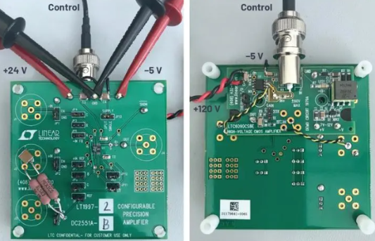
High Voltage Printed Circuit Boards (HV PCBs) represent a specialized segment of the PCB industry designed to handle voltages significantly higher than standard electronic circuits. While conventional PCBs typically operate below 50 volts, HV PCBs are engineered to withstand voltages ranging from hundreds to thousands of volts, with some specialized designs handling tens of thousands of volts.
The growing demand for HV PCBs stems from their critical role in modern power electronics, renewable energy systems, medical equipment, and industrial applications. These boards enable the safe and reliable operation of high-voltage circuits while maintaining compact form factors and efficient thermal management.
Key Design Considerations for HV PCBs
1. Creepage and Clearance Distances
The fundamental challenge in HV PCB design lies in preventing electrical breakdown between conductors. Two critical parameters govern this:
- Clearance: The shortest air path between two conductive elements
- Creepage: The shortest path along the surface of the insulation material between conductors
Design standards (such as IPC-2221 and IEC 60950) provide specific guidelines for minimum distances based on:
- Operating voltage (including peak transient voltages)
- Pollution degree of the operating environment
- Material group (comparative tracking index)
For example, at 1000V in a pollution degree 2 environment, typical requirements might be:
- 6.3mm clearance
- 12.5mm creepage
2. Material Selection
HV PCBs require specialized materials with:
- High dielectric strength (typically >20kV/mm)
- Excellent tracking resistance (CTI ≥ 600V)
- Low moisture absorption
- Thermal stability across operating ranges
Common substrate materials include:
- FR-4 (modified for HV applications)
- Polyimide
- PTFE-based materials
- Ceramic-filled composites
- Aluminum oxide (for hybrid designs)
3. Conductor Design
HV PCB traces require careful consideration of:
- Width (to handle current without excessive heating)
- Thickness (to minimize resistive losses)
- Corner radii (to prevent field concentration)
- Surface finish (to prevent dendritic growth)
A general rule for trace width in HV applications is to maintain at least 1mm per 100V to prevent surface tracking.
4. Layer Stackup and Insulation
Multilayer HV PCBs present unique challenges:
- Inner layer insulation must withstand potential partial discharges
- Buried vias require special attention to void-free plating
- Power and ground planes need appropriate spacing
- Sequential lamination may be required for thick insulation layers
5. Component Placement and Mounting
HV components require:
- Adequate spacing (considering both operational and maintenance safety)
- Special mounting techniques for large components
- Consideration of thermal expansion mismatches
- Proper termination techniques for HV connections
Manufacturing Challenges for HV PCBs
1. Material Handling
HV-grade materials often have:
- Different drilling parameters (ceramic-filled materials are abrasive)
- Special lamination requirements
- Unique desmear and hole preparation needs
2. Plating Quality
Voids or thin spots in plating can lead to:
- Partial discharge (corona effect)
- Premature breakdown
- Reduced product lifetime
3. Contamination Control
Even microscopic contamination can:
- Create leakage paths
- Reduce surface insulation resistance
- Promote dendritic growth
4. Testing and Quality Assurance
HV PCBs require specialized testing:
- Hi-pot testing (dielectric withstand test)
- Insulation resistance measurement
- Partial discharge testing
- Thermal cycling evaluation
Advanced HV PCB Technologies
1. Embedded Components
Integrating passive components within the PCB:
- Reduces surface arcing risks
- Improves reliability
- Saves space
2. Hybrid Construction
Combining different technologies:
- Thick-film printed resistors
- Ceramic substrates for critical areas
- Flexible sections for complex geometries
3. 3D Printed HV Structures
Emerging additive manufacturing techniques enable:
- Custom insulator geometries
- Graded dielectric structures
- Integrated cooling channels
4. Optical Isolation
Using light instead of electrons for signal transfer across potential barriers:
- Eliminates galvanic connections
- Provides superior isolation
- Reduces EMI susceptibility
Applications of HV PCBs
1. Power Electronics
- Switch-mode power supplies
- Inverters/converters
- Motor drives
- Power factor correction circuits
2. Renewable Energy Systems
- Solar microinverters
- Wind turbine controls
- Battery management systems
- Grid-tie equipment
3. Medical Equipment
- X-ray generators
- Electrosurgical units
- MRI systems
- Medical imaging devices
4. Industrial Equipment
- Plasma generators
- Electrostatic precipitators
- Laser systems
- Industrial automation controls
5. Automotive and Transportation
- Electric vehicle power systems
- Charging infrastructure
- Aerospace power distribution
- Railway traction systems
Reliability Considerations
HV PCBs face unique reliability challenges:
1. Partial Discharge
Microscopic discharges that:
- Erode materials over time
- Generate ozone and other corrosive byproducts
- Eventually lead to complete breakdown
Mitigation strategies include:
- Void-free manufacturing
- Proper material selection
- Conservative design margins
2. Surface Tracking
The formation of conductive paths across the surface due to:
- Contamination
- Humidity
- Material degradation
Prevention methods:
- Proper creepage distances
- Conformal coatings
- Regular cleaning (in serviceable equipment)
3. Thermal Management
High voltages often accompany:
- Significant current flows
- Dielectric losses
- Limited cooling options
Solutions include:
- Thermal vias
- Metal-core substrates
- Integrated heat spreaders
4. Mechanical Stress
HV designs often involve:
- Thick boards
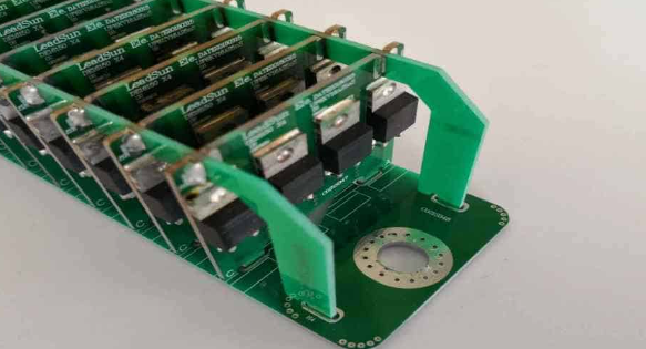
- Heavy components
- Large temperature swings
Design approaches:
- Stress-relief features
- Flexible sections
- Proper support structures
Future Trends in HV PCB Technology
1. Higher Voltage Densities
Ongoing research aims to:
- Reduce required spacings through better materials
- Develop nano-composite dielectrics
- Create self-healing insulation systems
2. Integrated Monitoring
Embedded sensors for:
- Partial discharge detection
- Temperature monitoring
- Insulation health assessment
3. Wide Bandgap Semiconductors
The adoption of SiC and GaN devices drives:
- Higher operating frequencies
- Increased voltage ratings
- New packaging challenges
4. Sustainable Materials
Development of:
- Bio-based dielectric materials
- Halogen-free flame retardants
- Recyclable substrate systems
Conclusion
High Voltage PCB design represents a sophisticated intersection of materials science, electrical engineering, and manufacturing technology. As power electronics continue to advance across industries, the demand for reliable, compact, and efficient HV PCBs will only grow. Successful HV PCB implementation requires careful attention to design rules, material selection, manufacturing processes, and application requirements.
Engineers working with HV PCBs must balance competing demands of performance, safety, reliability, and cost while staying abreast of evolving standards and emerging technologies. The future of HV PCBs promises both challenges and opportunities as voltages increase, form factors shrink, and applications diversify in our increasingly electrified world.