Implantable Medical Device PCB: Manufacturing Requirements for Cardiac Pacemaker Rigid-Flex Boards (2026)
Cardiac pacemaker PCBs represent the most demanding category of implantable medical device electronics—rigid-flex boards that must operate continuously for 7-15 years inside the human body, withstand fluid exposure, survive cardiac motion stress, and maintain absolute reliability. This guide covers the critical manufacturing requirements that separate standard rigid-flex fabrication from medical-grade implantable production.
Introduction
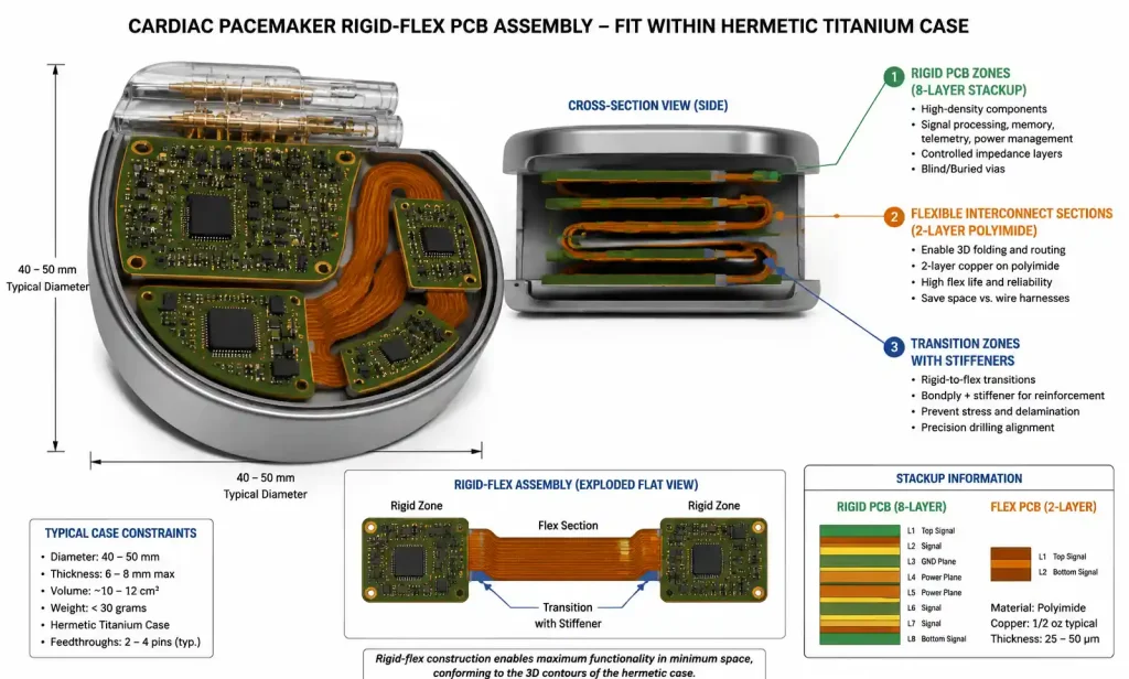
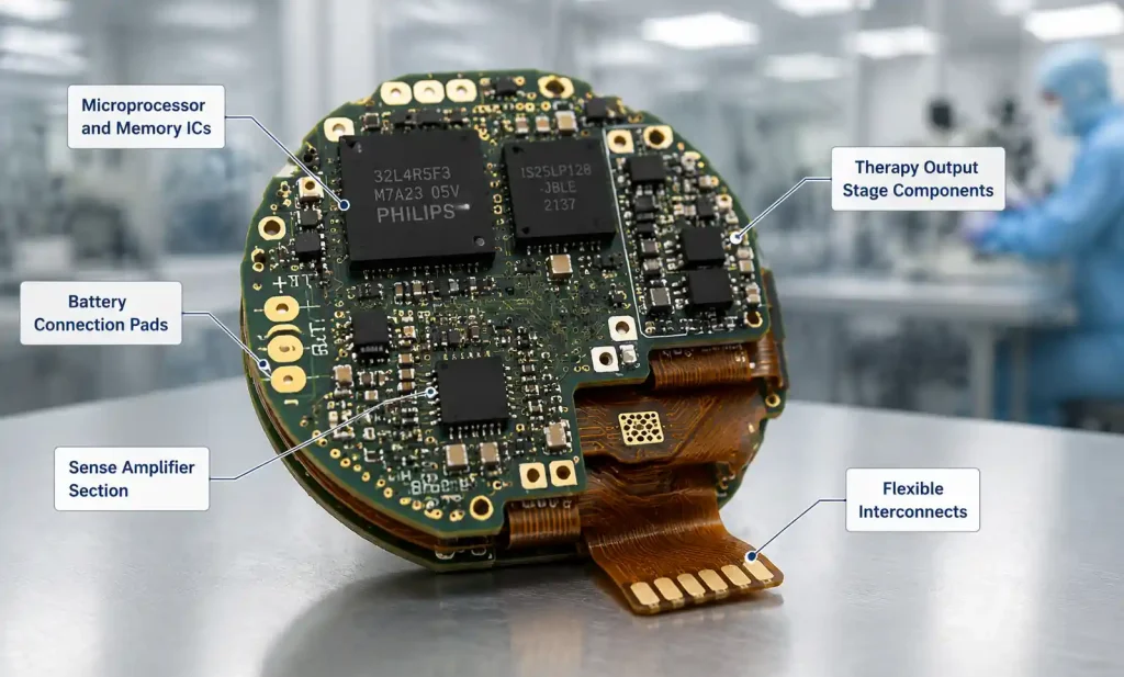
Cardiac pacemaker PCBs operate within hermetically sealed titanium cases (40-50mm diameter, 6-8mm thick), requiring extreme miniaturization with maximum reliability. Rigid sections house high-density components; flexible sections enable 3D folding within the case. Unlike consumer electronics where 99% yield is acceptable, pacemaker PCBs require near-zero defect rates, full material traceability, and compliance with IPC-6013 Class 3, FDA 21 CFR Part 820, and ISO 13485.
Critical Design Parameters
Trace Width and Spacing
- Rigid sections: 3mil trace width, 4mil spacing for signals; 5mil for power
- Flexible sections: 4mil trace width, 5mil spacing to prevent flexural fatigue
- High-voltage therapy (ICD): 15mil spacing for traces >100V, 20mil clearance to ground
Via Design for Flex-to-Rigid Transitions
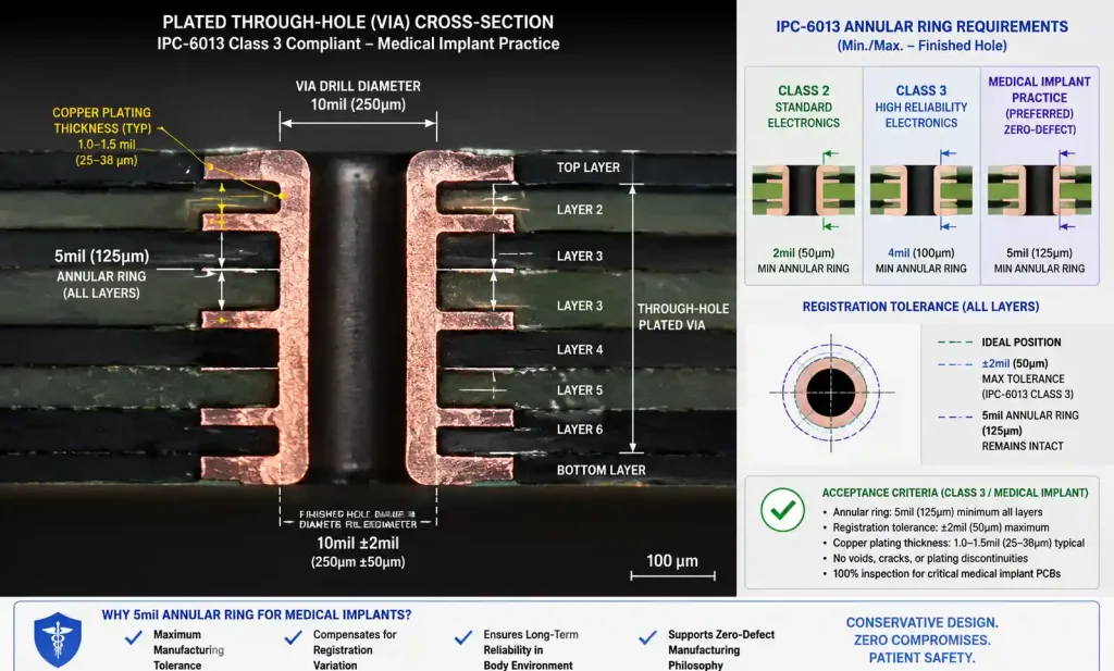
- Via diameter: 8mil finished hole (12mil pad)
- Annular ring: 4mil minimum (5mil preferred for Class 3)
- No vias within 20mil of rigid-flex boundary
- Resin-filled and copper-capped vias required in flex sections
- Stacked vias prohibited in flex regions; use staggered patterns with 30mil offset
Layer Stackup (Typical 8-Layer)
| Layer | Rigid Section | Flexible Section |
|---|---|---|
| 1 | Component side (signals + pads) | Signal routing (top) |
| 2 | Ground plane | — |
| 3 | Signal routing | — |
| 4 | Power plane (+3.3V, +1.8V) | — |
| 5 | Signal routing | — |
| 6 | Power plane (battery negative) | — |
| 7 | Signal routing | — |
| 8 | Component side (signals + pads) | Signal routing (bottom) |
Flexible sections carry low-speed signals, sense amplifier connections, and therapy paths. High-speed buses and sensitive analog remain in rigid sections.
Material Selection and Biocompatibility
| Material Type | Rigid Section | Flexible Section | Key Requirements |
|---|---|---|---|
| Substrate | Polyimide or high-Tg FR4 (≥180°C) | Polyimide (25-50μm) | ISO 10993-1 certified |
| Dielectric | PI-based prepreg | PI coverlay or LCP | Moisture absorption <0.5% |
| Copper foil | Rolled annealed (RA) | Rolled annealed (18-35μm) | >1M flex cycles |
| Coverlay | PI film with acrylic adhesive | PI film (12-25μm) | Halogen-free, low outgassing |
| Surface finish | ENIG (5-7μ” Au) | ENIG or Immersion Gold | Wire bondable, lead-free |
Polyimide: Medical-grade Kapton HN must pass ISO 10993-5 (cytotoxicity), -10 (sensitization), and -11 (systemic toxicity). Lot-specific biocompatibility test results required.
Adhesives: Acrylic-based bonding films or adhesiveless PI constructions preferred—eliminate outgassing and reduce thickness.
Copper distribution: Power layers use 2oz (70μm); signal layers 0.5-1oz (18-35μm); flex sections use 0.5oz RA copper. ICD therapy traces use 3oz copper with specialized insulation.
IPC-6013 Class 3 and Medical Standards
| Parameter | IPC-6013 Class 2 | IPC-6013 Class 3 | Medical Implant Practice |
|---|---|---|---|
| Minimum annular ring | 2mil (50μm) | 4mil (100μm) | 5mil (125μm) preferred |
| Min via aspect ratio | 8:1 | 6:1 | 4:1 (conservative) |
| Copper thickness tolerance | ±20% | ±15% | ±10% with lot verification |
| Registration tolerance | ±4mil | ±3mil | ±2mil (50μm) |
| Conductor spacing (external) | 4mil | 5mil | 6mil minimum for flex |
| Flex bend radius | 10× thickness | 6× thickness | 8× thickness for dynamic |
| Surface contamination | Visual | <1.56 μg/cm² NaCl eq. | <0.5 μg/cm² with docs |
Additional Medical Requirements
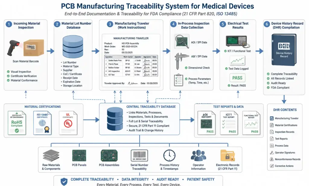
- Material traceability: Every lot documented in Device History Record (DHR)
- Process validation: All critical processes validated per FDA Guidance using worst-case conditions
- Environmental controls: ISO Class 7 (Class 10,000) cleanrooms with documented monitoring
- Operator certification: Documented training programs with written exams and qualification
DFM for Ultra-Reliable Assemblies
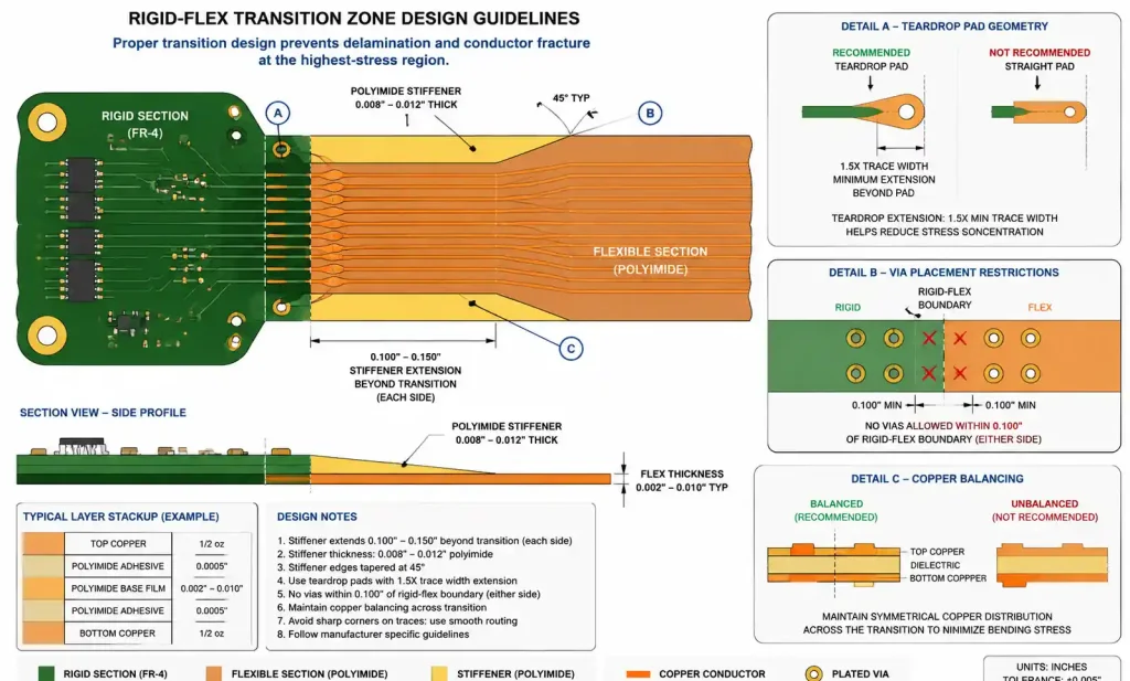
Transition Zone Design
- Stiffener placement: 0.008-0.012″ PI or FR4 stiffeners on both sides, extending 0.100-0.150″ beyond boundary, tapered 45°
- Teardrop pads: Required on all pads in flex section and within 0.200″ of boundary; extend ≥1.5× trace width
- Copper balancing: <30% copper density variation between top/bottom layers in transition zones
Flex Section Strain Relief
- Min bend radius: 8× total flex thickness for dynamic flex
- Trace routing: Route traces perpendicular to bend axis when possible
- Via avoidance: No vias within 0.100″ of any bend axis
- Anchor points: Stiffen both ends of dynamic flex sections
Coverlay and Solder Mask
- Coverlay opening: +0.004″/-0.002″ from pad edge
- Solder mask clearance: 3mil minimum from pad edge
- Solder mask thickness: 0.8-1.2mil over copper
- Coverlay registration: ±0.003″
Panelization
- Panel size: 12″ × 18″ or smaller for cleanroom equipment
- Breakaway: Routed with 0.125″ tabs and stress relief holes; V-groove not recommended (particles)
- Fiducials: 4 global fiducials (50mil bare copper circles) plus local for fine-pitch components
Testing and Traceability Requirements {#6-testing-and-traceability-requirements}
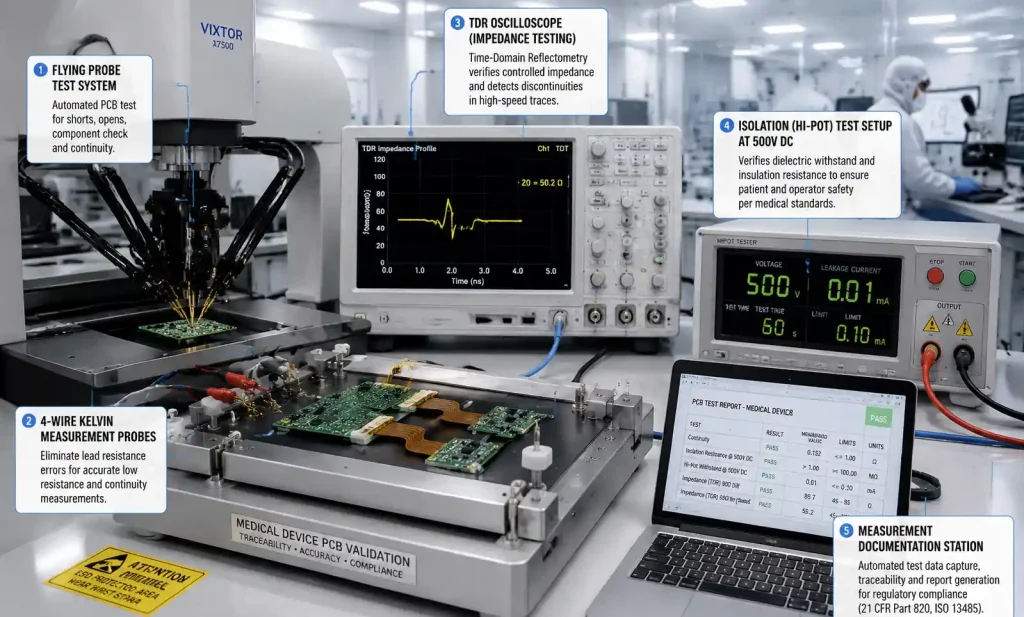
Electrical Testing
| Test Type | Standard | Medical Implant Requirement | Acceptance Criteria |
|---|---|---|---|
| Continuity | Flying probe | 4-wire Kelvin, 100% nets | <10Ω signal, <5Ω power |
| Isolation | 100V DC, 10MΩ | 500V DC, 100MΩ | >100MΩ between isolated nets |
| Impedance | TDR sampling 10-20% | TDR 100% of controlled nets | ±10% target |
| Hi-Pot | 250V AC, 1s | 1000V DC, 5s | <1μA leakage |
| Microsection | 1 sample/lot | 3 samples/panel, 20+ measurements | IPC-6013 Class 3 |
Flex endurance testing: IPC-TM-650 2.4.5.1 — 100,000 cycles at min bend radius for dynamic flex; 1,000 cycles for static.
Material Verification and Lot Traceability
Every incoming material lot verified: copper foil (tensile, elongation, roughness), polyimide film (Tg, CTE, moisture absorption, Dk), prepreg/adhesive (resin content, flow, gel time). Certifications include manufacturer, lot#, test results, biocompatibility reports, RoHS/REACH declarations.
Device History Record (DHR)
Each board requires complete DHR: BOM with lot numbers, manufacturing travelers (operator signatures/timestamps), in-process inspection results, all test data, non-conformance reports, final inspection signature. Enables full traceability from finished device to raw materials.
FAQ
What is typical lead time for medical-grade rigid-flex PCBs? 6-10 weeks for prototypes (10-50 pieces); 4-6 weeks for production. Extended due to material testing, in-process holds, comprehensive testing, and documentation. First-time builds: 12-16 weeks.
Can standard PCB manufacturers produce medical implant boards? Requires ISO 13485 certification, FDA registration, cleanroom facilities, validated processes, operator training programs, and material traceability systems. Work with ISO 13485-certified manufacturers with medical device production history.
How does cost compare to commercial rigid-flex? Medical boards cost 3-5× more due to biocompatibility-certified materials, extensive testing/documentation (20-30% extra), lower volumes, cleanroom overhead, and traceability. 8-layer pacemaker board: $800-1,500 for 25-piece prototypes; $200-400 for 500-piece production.
What are the most common DFM issues? Insufficient transition zone clearance (plating fractures), copper imbalance (panel warping), inadequate stiffener design (delamination), coverlay openings too close to pad edges, via aspect ratios >4:1, insufficient strain relief in flex sections.
What surface finishes besides ENIG are acceptable? ENEPIG offers superior wire bond reliability but costs 30-40% more. Immersion Silver (limited shelf life, no wire bonding). HASL, OSP, Immersion Tin generally not used for implantable devices.
Static vs dynamic flex bend radius? Static (bent once): 6× total thickness per IPC-6013 Class 3. Dynamic (repeated): 10-12× total thickness for >1M cycles. Cardiac pacemakers rarely use dynamic flex due to reliability concerns.
What biocompatibility tests are required? ISO 10993 series: -5 (cytotoxicity), -10 (sensitization), -11 (systemic toxicity), -3 (genotoxicity). Chronic implants require subchronic/chronic toxicity testing. Materials tested in final processed form.
Can blind vias or microvias be used? Yes, for routing density in rigid sections. Restrictions: no microvias in flex sections or within 0.100″ of rigid-flex boundaries; stacked microvias require resin filling; via-in-pad requires copper filling and planarization.
Conclusion
Manufacturing rigid-flex PCBs for cardiac pacemakers represents the highest tier of PCB fabrication, combining extreme reliability, biocompatibility, and rigorous quality documentation. Key differentiators:
- Material selection: Biocompatibility-certified materials with full lot traceability; polyimide constructions with proven long-term stability
- Design conservatism: IPC-6013 Class 3 as baseline; tighten annular rings, via aspect ratios, and flex section spacing for additional reliability margin
- Transition zone engineering: The rigid-flex interface is the highest-stress region; proper stiffener design, copper balancing, and strain relief prevent field failures
- Process validation and documentation: FDA-validated processes with SPC; complete Device History Records for every board
Next steps: Conduct comprehensive DFM review before prototype fabrication. For manufacturers, begin with ISO 13485 certification and establish validated processes for drilling, plating, and lamination. Partner with material suppliers who provide biocompatibility documentation and technical support. The investment in rigorous design rules, material selection, and quality processes is not optional—it’s the ethical foundation of the medical device industry.