
Skip to content
Andwin Circuits
  • Home
  • ProductsExpand
    • HDI multilayer PCB
    • Rigid Flex PCB
    • Flex pcb
    • Special PCBExpand
      • High Frequency PCBExpand
        • Rogers RO4350B PCB
        • Rogers RO4003 pcb
        • Rogers RO3003 PCB
        • Rogers 5880 PCB
        • DICLAD 527 PCB
        • Taconic TLX series
        • Taconic TLX-8 RF PCB
        • Taconic TLX-9 RF PCB
      • High speed pcbExpand
        • Megtron 6 High Speed PCB
        • TU-872 SLK Sp High Speed
      • High TG PCBExpand
        • SHENGYI SH260 PCB
        • ISOLA 370HR PCB
        • ISOLA IS410 PCB
        • ISOLA IS420 PCB
      • Heavy copper PCB
      • Copper coin pcb
      • Copper inlay PCB
    • Metal Core PCBExpand
      • Copper core pcb
      • Aluminum PCB
      • 2 Layers Aluminum PCB
      • Direct thermal MCPCB
      • 2 Layers Direct Thermal
    • Ceramic PCBExpand
      • DPC ceramic PCB
      • DBC ceramic PCB
      • Thick film Ceramic PCB
      • Al2O3 Alumina PCB
      • AIN ALN ceramic PCB
      • IGBT Ceramic PCB
  • ServiceExpand
    • PCB Assembly
    • Quick turn PCB assembly
    • PCBA conformal coating
  • IndustryExpand
    • Telecommunication
    • IoT and Wireless
    • Industrial Control
    • Thermal management
    • Power and Energy
    • IC test board
    • Automative
    • Medical
  • CapabilityExpand
    • Rigid PCB
    • Rigid flex PCB
    • Metal core PCB
    • PCB Assembly
  • TechnologyExpand
    • Blogs
    • Via in pad
    • PCB E-test
    • PCB stack up
    • MCPCB panelization
    • Controlled impedance PCB
  • AboutExpand
    • About us
    • Certification
    • Factory Tour
  • Contact
Andwin Circuits
Home / Loss solution for PCB wiring in high-speed circuit design

Loss solution for PCB wiring in high-speed circuit design

ByGrace June 27, 2024June 27, 2024

The results of the eye diagram also show that the effect is obvious. In fact, in the process of product design, PCB wiring is often not something you can modify as you want, which involves collaboration between many aspects and departments; changing PCB materials is also very troublesome, and it can only be adjusted after the board is changed. Therefore, sometimes you can change your mind and consider the problem of the path, which may have unexpected results.

Some time ago, we wrote an article about the signal integrity of USB3.0, talking about the selection of one of the components. It happened that a friend encountered a similar problem. Due to excessive loss, he kept adjusting the PCB wiring length, and the length was compressed by 1 inch, but it still didn’t work; he changed the PCB material, but the problem was not solved well. In fact, the problem finally found was the selection of materials, because many times the loss caused by PCB wiring is much smaller than the loss of materials, which many engineers have not noticed. Because many engineers who don’t know much about high-speed circuit design don’t have a clear understanding of component loss, they don’t know where to start, or they think that the PCB wiring is so long and the connector or other components are so small, so they take it for granted that the loss is small…

Contact us for PCB quote now |

First, let’s take a rough look at the loss comparison of a common choke, a connector, and a 5-inch PCB wiring (ordinary FR4 material)
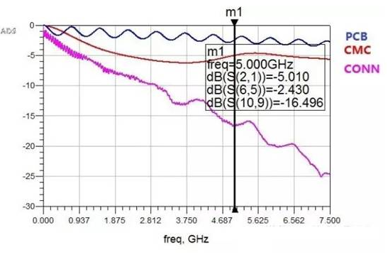
Comparing the 5GHz frequency, it is obvious that the connector has the highest loss, followed by the common choke, and the 5-inch PCB wiring. At this time, if the connector and common choke you choose are relatively poor, no matter how you adjust the PCB wiring, it may not meet your design requirements. Even if you change the material, the effect of reducing the loss will definitely not bring much improvement, compared to its proportion in the loss. But if you can change the common choke or connector, the effect will be obvious. The following is a loss comparison of changing a common choke.
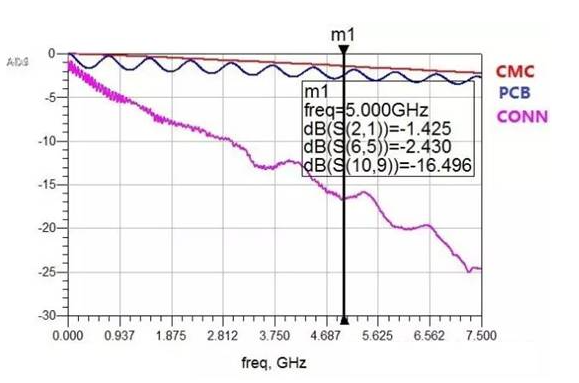
Compared with the 5GHz frequency, the loss of Common choke is greatly reduced, which is completely incomparable to PCB wiring or changing PCB materials. Of course, if the connector is improved, the effect may be more obvious. I will not go into details here. Interested engineers can try it by themselves.

Of course, you can also compare the active eye diagram simulation. Figure 3 is the eye diagram before the device is changed, and Figure 4 is the eye diagram after the device is changed:
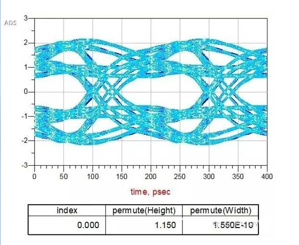
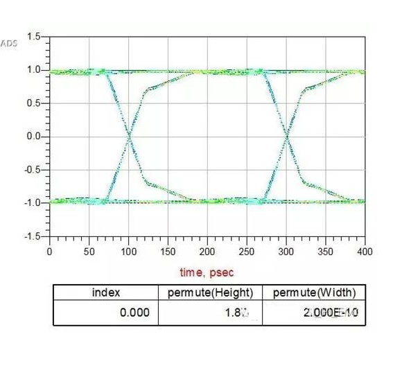
The results of the eye diagram also show that the effect is obvious. In fact, in the process of product design, PCB wiring is often not something you can modify as you want, which involves collaboration between many aspects and departments; changing PCB materials is also very troublesome, and it can only be adjusted after the board is changed. Therefore, sometimes you can change your mind and consider the problem of the path. At this time, there may be unexpected results.

Contact us for PCB quote now |
Post Tags: #High speed PCB#pcb#pcb design

Post navigation

Previous Previous
How to achieve reliable and efficient industrial PCB links
NextContinue
Peak current and decoupling capacitors during PCB layout

Search

Search

Products

  • HDI Multilayer PCB
  • Rigid Flex PCB
  • Flex pcb
  • High Frequency PCB
  • High speed pcb
  • Heavy copper PCB
  • Metal Core PCB
  • Ceramic PCB

Address

Andwin Circuits Co.,Limited
Email: sales@andwinpcb.com
Tel: +86 755 2832 9394
Fax:+86 755 2992  6717
ADD:1-2F-1217,HouDeQun Industrial park,
NanTing RD NO.56,ShaJing,BaoAn,Shenzhen 518104,GuangDong,China

Products

  • HDI Multilayer PCB
  • Rigid Flex PCB
  • Flex pcb
  • High Frequency PCB
  • High speed pcb
  • Heavy copper PCB
  • Metal Core PCB
  • Ceramic PCB

Technology

  • Blogs
  • Via in pad
  • PCB E-test
  • PCB stack up
  • Metal core PCB panelization
  • Controlled impedance PCB

CERTIFICATION

Certification >>


Copyright© 2003 - 2026 Andwin | All Rights Reserved | Powered by Andwin

Scroll to top
  • Home
  • Products
    • HDI multilayer PCB
    • Rigid Flex PCB
    • Flex pcb
    • Special PCB
      • High Frequency PCB
        • Rogers RO4350B PCB
        • Rogers RO4003 pcb
        • Rogers RO3003 PCB
        • Rogers 5880 PCB
        • DICLAD 527 PCB
        • Taconic TLX series
        • Taconic TLX-8 RF PCB
        • Taconic TLX-9 RF PCB
      • High speed pcb
        • Megtron 6 High Speed PCB
        • TU-872 SLK Sp High Speed
      • High TG PCB
        • SHENGYI SH260 PCB
        • ISOLA 370HR PCB
        • ISOLA IS410 PCB
        • ISOLA IS420 PCB
      • Heavy copper PCB
      • Copper coin pcb
      • Copper inlay PCB
    • Metal Core PCB
      • Copper core pcb
      • Aluminum PCB
      • 2 Layers Aluminum PCB
      • Direct thermal MCPCB
      • 2 Layers Direct Thermal
    • Ceramic PCB
      • DPC ceramic PCB
      • DBC ceramic PCB
      • Thick film Ceramic PCB
      • Al2O3 Alumina PCB
      • AIN ALN ceramic PCB
      • IGBT Ceramic PCB
  • Service
    • PCB Assembly
    • Quick turn PCB assembly
    • PCBA conformal coating
  • Industry
    • Telecommunication
    • IoT and Wireless
    • Industrial Control
    • Thermal management
    • Power and Energy
    • IC test board
    • Automative
    • Medical
  • Capability
    • Rigid PCB
    • Rigid flex PCB
    • Metal core PCB
    • PCB Assembly
  • Technology
    • Blogs
    • Via in pad
    • PCB E-test
    • PCB stack up
    • MCPCB panelization
    • Controlled impedance PCB
  • About
    • About us
    • Certification
    • Factory Tour
  • Contact
Search