
Metal Core PCB for Medical Equipment: Reliability and Thermal Stability Requirements
Medical equipment demands exceptional reliability, precise thermal management, and long operational life. Metal Core PCBs have become the go-to choice for devices that generate significant heat – LED surgical lighting, high-power diagnostic imaging, and the like. This guide covers the critical design parameters, material requirements, and thermal specs you need to keep your medical MCPCB reliable and compliant.
Why Metal Core PCB for Medical Applications
Medical devices can’t afford thermal failures. Patient safety and measurement accuracy depend on stable operation. Standard FR4 PCBs can’t dissipate heat efficiently from high-power LEDs, power converters, or motor drivers. MCPCBs fix this by swapping the FR4 substrate for a metal base – aluminum or copper – that conducts heat 8-10 times better.
The metal base acts as an integrated heat spreader, pulling heat from components to the chassis or heatsink. This matters for medical applications where temperature stability affects LED color consistency in surgical lighting, measurement accuracy, and component longevity in 24/7 operation. Beyond thermal benefits, MCPCBs offer better dimensional stability under thermal cycling and greater mechanical strength.
Critical Material Properties for Medical MCPCBs
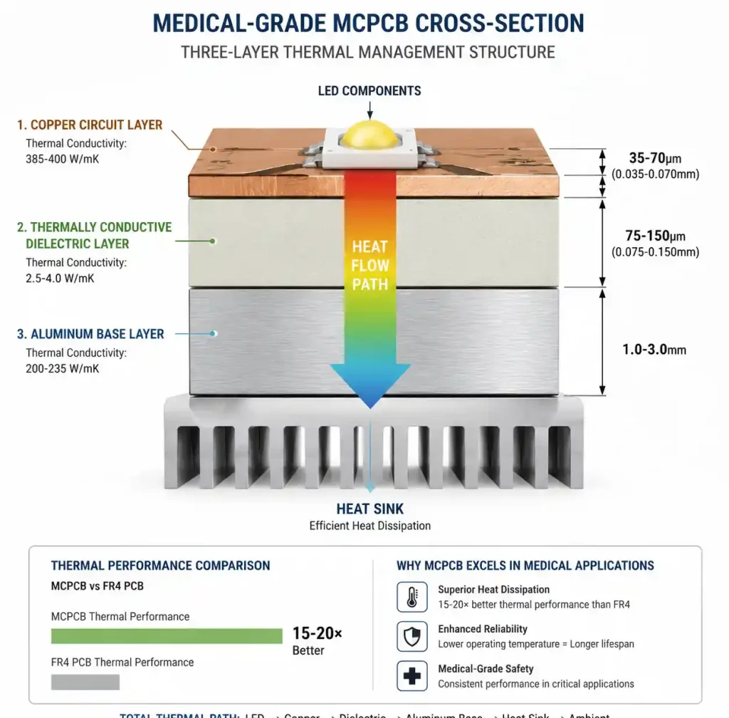
Material selection drives thermal performance, reliability, and regulatory compliance. Medical MCPCBs stack up as: copper circuit layer, thermally conductive dielectric, and metal base. Each layer needs to meet specific thermal, electrical, and mechanical requirements.
Metal Base Layer Selection
Aluminum 5052 or 6061 is standard for medical MCPCBs, running 160-200 W/mK thermal conductivity at reasonable cost. Aluminum gives you good heat dissipation, lightweight (important for portable devices), and natural EMI shielding. For extreme thermal demands – high-power surgical lasers or dense LED arrays – copper base MCPCBs hit 400 W/mK, but cost more and weigh more.
Base thickness runs 1.0mm to 3.0mm depending on mechanical needs and thermal mass. Medical devices needing UL recognition need aluminum alloys that meet UL 94 flammability. Surface finish matters for thermal interface: anodized aluminum gives electrical isolation and corrosion resistance; bare aluminum maximizes thermal contact with heatsinks.
Dielectric Layer Requirements
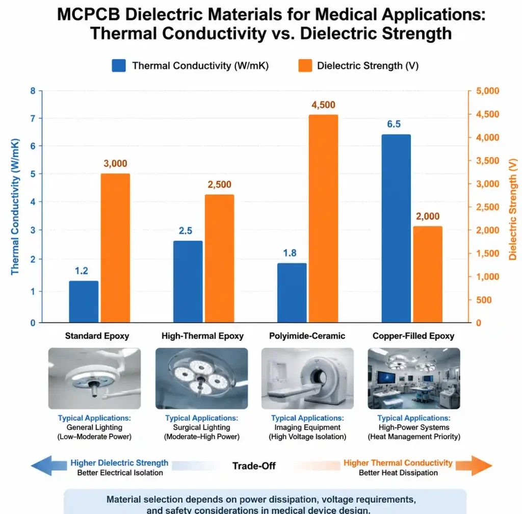
The dielectric is the critical layer – it sets thermal resistance while isolating the circuit electrically from the metal base. Medical applications need dielectric materials with thermal conductivity above 2.0 W/mK and breakdown voltage over 3000V. Epoxy-based dielectrics with ceramic fillers are standard, running 1.5 to 3.0 W/mK. For high-reliability medical gear, polyimide-based dielectrics offer better thermal stability and lower thermal resistance.
Dielectric thickness is a balancing act – thinner (50-100µm) gives better heat transfer but lower breakdown voltage. Medical equipment typically uses 75-150µm to meet IEC 60601 safety standards while keeping thermal conductivity below 1.0°C/W for typical LED apps.
| Dielectric Material | Thermal Conductivity | Dielectric Strength | Typical Thickness | Medical Application |
|---|---|---|---|---|
| Standard Epoxy | 1.5-2.0 W/mK | 3000-3500 V | 75-100 µm | General medical lighting |
| High-thermal Epoxy | 2.0-3.0 W/mK | 2800-3200 V | 50-75 µm | High-power LED arrays |
| Polyimide-ceramic | 2.5-4.0 W/mK | 3500-4000 V | 75-125 µm | Surgical lighting, imaging |
| Copper-filled Epoxy | 3.0-5.0 W/mK | 2500-3000 V | 50-100 µm | Maximum heat dissipation |
Polyimide-ceramic is our pick when long-term thermal cycling matters more than upfront cost – think surgical suite gear running 10+ years continuous. If you need UL certification, make sure your dielectric has UL 94 V-0 rating and meets biocompatibility requirements if the PCB assembly touches implantable device manufacturing. For implantable sensor applications, flex PCBs in medical devices offer additional design flexibility for miniaturized assemblies.
Thermal Performance Specifications
Medical MCPCB thermal management comes down to three numbers: thermal resistance, junction temperature, and thermal cycling performance. Get these right and components stay within limits, measurements stay accurate, and the gear keeps running.
Thermal Resistance Calculation
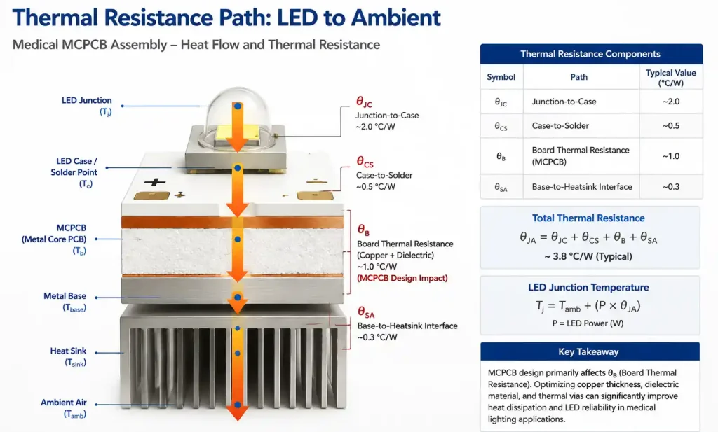
Total thermal resistance from LED junction to ambient (θJA) sets operating temperature. The path includes: junction-to-case (θJC, from the datasheet), case-to-board through solder (θCS), board thermal resistance through copper and dielectric (θB), and metal-base-to-heatsink interface (θSA). The MCPCB mainly affects θB, which depends on copper thickness, dielectric conductivity, and dielectric thickness.
For a typical medical LED with 1oz copper and 75µm dielectric at 2.5 W/mK, board thermal resistance runs about 0.4-0.6°C/W per cm². Same design on FR4? 8-12°C/W per cm². That 15-20× improvement lets medical LEDs run at higher currents without exceeding 125°C max junction temp – more light output, longer L70 lifetime.
Junction Temperature Management
Medical lighting needs to keep LED junction temps below manufacturer limits to maintain color stability and prevent early failure. Surgical lighting requires CRI >95 and color temp stability within ±200K over the device lifetime. Junction temp directly affects forward voltage and color point – thermal management is critical for medical color accuracy.
Design your MCPCB to keep junction temp at least 20°C below absolute max. For medical devices running in 25°C ambient with 40°C enclosure possible, target 100°C max junction for 125°C-rated LEDs. This gives margin for thermal interface degradation, dust on heatsinks, and worst-case ambient – while hitting 50,000+ hour L70 lifetime.
Medical Compliance and Reliability Requirements
Medical gear faces tougher rules than commercial electronics. Know these standards upfront to avoid costly redesigns.
IEC 60601 Electrical Safety
IEC 60601-1 is the main safety standard for medical electrical equipment. For MCPCBs, key requirements cover electrical isolation, leakage current, and protective earth connections. The dielectric must provide adequate insulation between the circuit and grounded metal base. Patient-applied parts need reinforced insulation with creepage and clearance based on working voltage and pollution degree.
Most medical MCPCBs use the metal base as protective earth. Design needs robust ground connections from the metal layer to chassis ground. Touch current and patient leakage testing will verify insulation holds even under single-fault conditions.
Material Compliance Requirements
Medical devices need material compliance beyond standard PCB certs. UL recognition for the complete MCPCB (not just individual materials) verifies flammability and electrical properties. RoHS compliance is mandatory for EU medical equipment. For MRI environments, avoid magnetic materials – standard aluminum MCPCBs are fine, but verify no magnetic fillers in the dielectric.
If the PCB assembly touches patient contact areas, biocompatibility testing per ISO 10993 may be required. Even if enclosed, contract manufacturers increasingly want material declarations and biocompatibility assessments for all components.
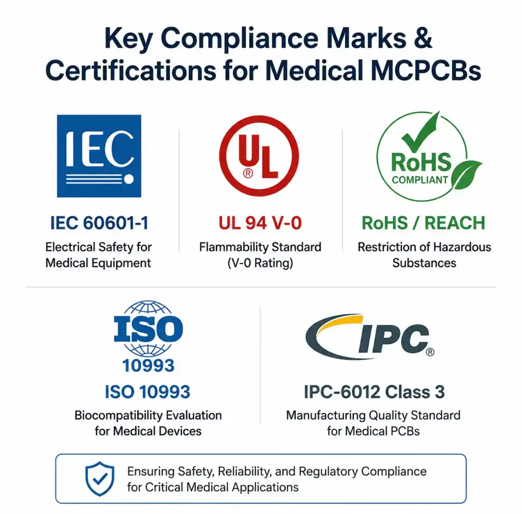
| Compliance Standard | Requirement Type | Key Parameter | Typical Test/Verification |
|---|---|---|---|
| IEC 60601-1 | Electrical Safety | Dielectric withstand >3000V AC | Hi-pot testing at 1.5× + 1000V |
| UL 94 | Flammability | V-0 rating | Vertical burn test |
| RoHS / REACH | Hazardous substance | Lead-free, compliant materials | Material declaration + XRF |
| ISO 10993 | Biocompatibility | Non-cytotoxic materials | Extract testing per device class |
| IPC-6012 Class 3 | Manufacturing quality | High reliability construction | Visual inspection + microsection |
Medical MCPCBs typically need IPC-6012 Class 3 manufacturing – tighter annular ring (4 mil min vs 2 mil for Class 2), stricter visual inspection, and microsection analysis for dielectric adhesion and plating quality. Make sure your PCB manufacturer has ISO 13485 certification and can provide Class 3 certification.
Design Rules and Layout Considerations
MCPCB layout differs from standard multilayer boards. The metal base creates opportunities and constraints that affect component placement, thermal via design, and assembly.
Component Placement and Thermal Zones
Place high-power components (LEDs, power ICs, MOSFETs) to maximize thermal spreading through the metal base. For LED arrays, keep uniform spacing – thermal imaging shows LEDs closer than 10mm on aluminum MCPCBs create compound heating that raises junction temp 15-20°C above isolated placement. High-density medical lighting needs thicker metal base or copper-core.
Keep temperature-sensitive parts (precision references, low-drift resistors, Hall sensors) at least 20mm from high-power zones. The metal base spreads heat laterally, which can raise ambient across the whole board. For mixed-signal medical devices with power and precision analog circuits, consider thermal barriers (slots or cutouts) to isolate zones – though this reduces mechanical strength and may need chassis support.
Thermal Via Strategy
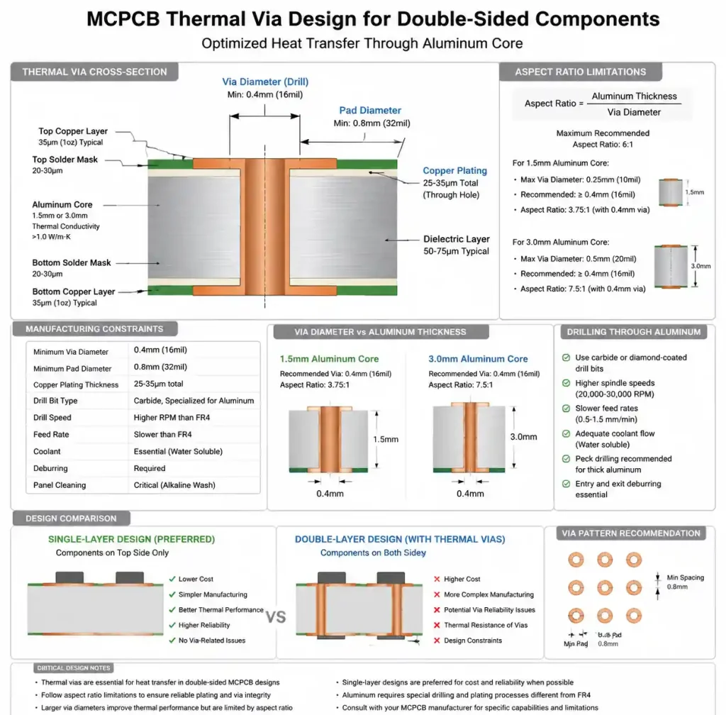
MCPCBs are typically single or double-layer – the metal base is the primary heatsink. Thermal connection from component pads to the base happens through the dielectric. For double-sided designs, vias through the metal base become necessary.
Drilling aluminum requires different processes than FR4. Via diameter needs at least 0.4mm for clean drilling, with 0.8mm min pad diameter. Metal layer thickness limits aspect ratio – 1.5mm aluminum works fine, 3.0mm may need larger vias. Plating through aluminum is tricky since it doesn’t accept copper plating directly. Manufacturers use special anodizing and seeding processes, which add cost and lead time. For cost-sensitive medical devices, stick with single-layer MCPCBs without metal-base vias.
DFM Considerations for Medical MCPCBs
MCPCB manufacturing has specific DFM challenges that affect yield, cost, and reliability. Know these constraints upfront.
Line Width and Spacing
Copper circuit formation on MCPCBs is similar to standard PCBs, but the rigid metal base affects handling and etching uniformity. Minimum trace/space depends on copper weight – 1oz (35µm) supports 4/4 mil at most shops, 2oz (70µm) needs 6/6 mil. Medical Class 3 designs should target 8/8 mil minimum for margin.
The metal base gives excellent dimensional stability, but thermal expansion mismatch between aluminum and copper creates internal stress that increases registration errors. Critical medical measurement traces (precision analog, differential pairs) should specify ±2 mil width tolerance for MCPCB process variation.
Assembly and Rework Challenges
The metal base acts as a massive thermal sink during soldering. Reflow profiles need longer preheat – 90-120 seconds versus 60-90 for FR4, with conveyor speed reduced 30-40%. For lead-free SAC305, extend time above liquidus to ensure complete wetting.
Rework is harder – the base pulls heat away, making hand soldering difficult without specialized high-wattage gear. For field-serviceable medical devices, design modular assemblies where the MCPCB replaces as a unit. If field rework is absolutely necessary, specify preheating the whole board to 100-120°C before component removal.
FAQ
Q: What’s the difference between aluminum-core and copper-core PCBs for medical use?
Aluminum-core runs 160-200 W/mK at lower cost and weight – fine for most medical LED lighting. Copper-core hits 400 W/mK for extreme heat dissipation but costs 3-4× more and weighs more. Only spec copper-core when thermal modeling shows aluminum can’t keep junction temps within limits. For a detailed comparison, see our guide on aluminum PCB vs metal core PCB for heat dissipation and material selection.
Q: How do I choose the metal base thickness for my device?
Base thickness gives thermal mass and mechanical rigidity. Starting guidelines: 1.0mm aluminum for LED arrays under 10W with active cooling; 1.5mm for 10-30W; 2.0mm for 30-50W; 3.0mm for higher power or passive cooling. Portable devices may need 1.0mm to save weight, compensating with better heatsink design.
Q: Can MCPCBs meet IPC Class 3 for medical devices?
Yes, qualified shops produce MCPCBs to IPC-6012 Class 3. Key differences: 4 mil min annular ring, enhanced visual inspection, mandatory microsection analysis of dielectric adhesion, and strict process controls. Specify Class 3 in your fab drawing and verify your manufacturer has ISO 13485 certification.
Q: What thermal interface material should I use between MCPCB and heatsink?
Thermal grease gives 0.5-1.0°C/W but needs periodic reapplication – not great for sealed medical devices. Thermal pads (1.0-2.0°C/W) provide consistent long-term performance with no maintenance. For 10+ year continuous operation, use gap-filling pads rated >100,000 hours. Apply 30-50 PSI even pressure with torque-controlled fasteners.
Q: Do MCPCBs need special considerations for medical sterilization?
If your device needs sterilization, verify materials can handle it. Autoclave (121-134°C steam) – make sure dielectric Tg >150°C and moisture absorption won’t degrade thermal conductivity. EtO gas is compatible with most materials. UV/gamma radiation can degrade some epoxies – check with your manufacturer. Most medical MCPCBs are in sealed enclosures, but contract manufacturers may still require this verification.
Conclusion
Reliable medical MCPCBs come down to three things: dielectric with >2.5 W/mK and UL recognition, LED junction temps at least 20°C below max, and IPC-6012 Class 3 manufacturing with ISO 13485-certified suppliers. Verify your thermal calcs, check IEC 60601 creepage, and get your fabricator involved early. Most shops offer free DFM review – take advantage of it before you lock in the layout. For related high-reliability applications, our guide on 5G base station RF modules covers Rogers 4350B metal core PCB solutions for demanding RF environments.