
High Thermal Conductivity Aluminum PCB vs Metal Core PCB: LED Heat Dissipation Design Material Selection
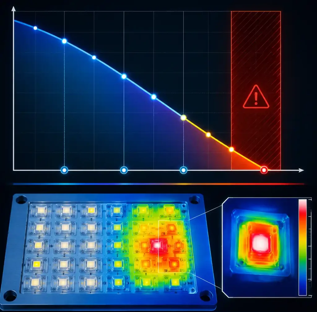
Thermal management is what separates LED designs that last 50,000 hours from those that fail in the first year. For every 10°C increase in junction temperature above the rated maximum, LED lifespan drops by roughly 50%. Standard FR4 with its 0.3 W/m·K thermal conductivity can’t move heat fast enough. Working with an experienced PCB manufacturer that understands metal-core fabrication is essential—aluminum and copper core boards require different processing than standard FR4, and not every shop can handle the drilling, routing, and dielectric lamination requirements. Here’s how to choose between aluminum PCB and metal core PCB for your LED application.
Key Differences at a Glance
“Aluminum PCB” and “metal core PCB” are often used interchangeably, but there’s a distinction. Aluminum PCB is a type of MCPCB where the metal substrate is specifically aluminum. MCPCB is the broader category—aluminum, copper, or steel alloys as the core.
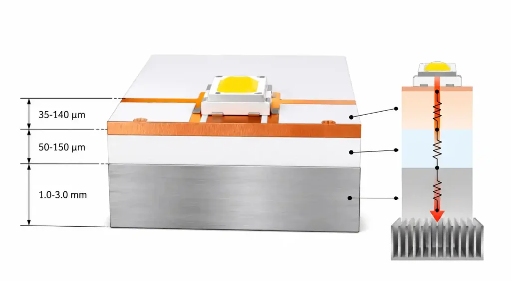
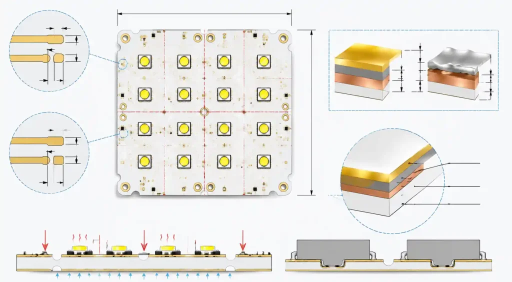
Aluminum PCB: Aluminum base layer (1.0–3.0 mm), thermally conductive dielectric (20–200 μm), copper circuit layer (1–4 oz). The aluminum provides the thermal path and accounts for 90%+ of board thickness.
Metal Core PCB (MCPCB): Any PCB with a metal substrate core. Copper-core boards hit 400 W/m·K thermal conductivity but cost significantly more. Steel-core boards are used where electromagnetic shielding is needed.
For LED thermal design, aluminum MCPCBs dominate—optimal balance of thermal performance (1–8 W/m·K dielectric thermal conductivity), cost, and weight. Copper-core is reserved for extreme power densities above 50 W/in² where aluminum can’t keep up.
Thermal Performance Parameter Comparison
The dielectric layer is the thermal bottleneck. Its thermal conductivity and thickness determine how effectively heat moves from the LED junction to the metal core.
| Parameter | Standard Aluminum PCB | High Thermal Aluminum PCB | Copper Core MCPCB | FR4 (Reference) |
|---|---|---|---|---|
| Dielectric thermal conductivity | 1.0–2.0 W/m·K | 3.0–8.0 W/m·K | 3.0–12.0 W/m·K | 0.3 W/m·K |
| Dielectric thickness | 75–150 μm | 50–100 μm | 50–150 μm | 1.6 mm (total) |
| Thermal resistance (typical) | 2.0–4.0 °C·cm²/W | 0.5–1.5 °C·cm²/W | 0.3–1.0 °C·cm²/W | >10 °C·cm²/W |
| Breakdown voltage | >3000 V | >2500 V | >2500 V | >3000 V |
| Operating temperature | -40°C to +130°C | -40°C to +150°C | -40°C to +150°C | -40°C to +130°C |
| Material cost (relative) | 1× | 1.5–2.5× | 4–6× | 0.5× |
High thermal aluminum PCBs cut thermal resistance by 60–75% compared to standard aluminum PCBs, but cost 1.5–2.5× more. For LED applications where warranty costs and field failures matter, that premium usually pays for itself within the first year.
Thermal resistance (°C·cm²/W) is more useful than thermal conductivity alone—it accounts for both material conductivity and layer thickness. A thinner dielectric with moderate conductivity can outperform a thicker layer with higher conductivity.
Dielectric Material Technology Breakdown
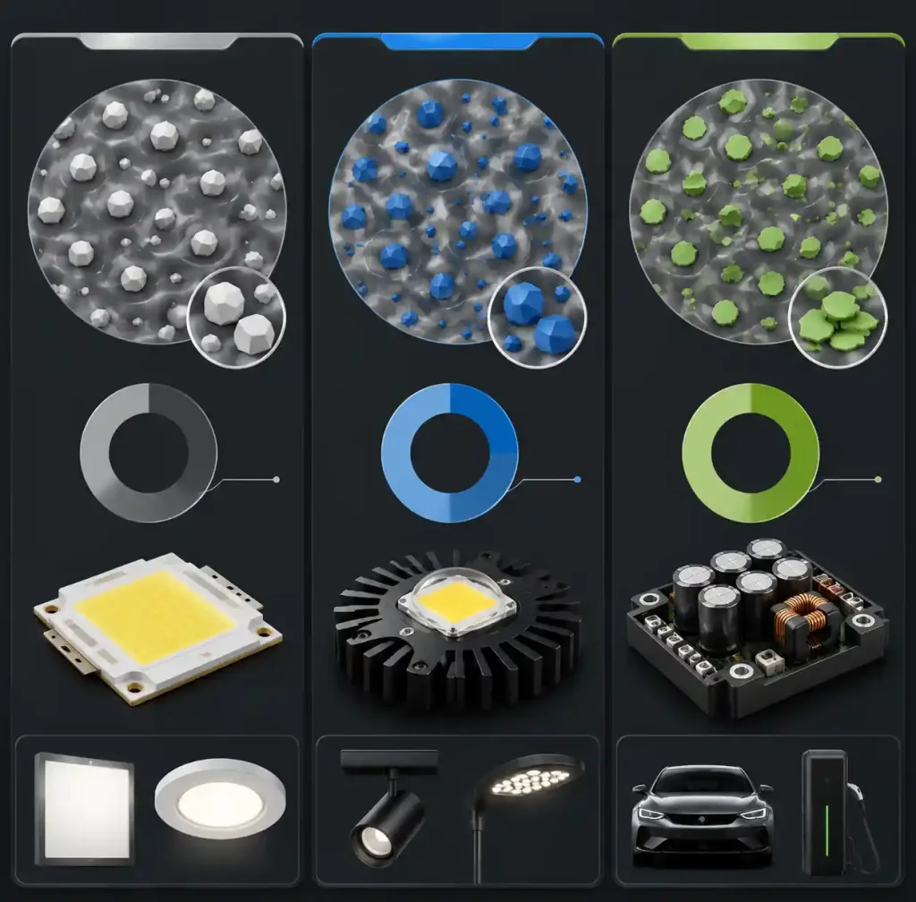
The dielectric layer uses ceramic-filled polymer composites—epoxy or polyimide resin filled with ceramic particles (aluminum oxide, aluminum nitride, boron nitride, or silicon carbide).
Standard thermal dielectric (1.0–2.0 W/m·K): Epoxy with 40–60% aluminum oxide. Cost-sensitive LED applications like bulbs, downlights, and low-power signage. Dielectric thickness is 100–150 μm for >3000V breakdown.
High thermal dielectric (3.0–5.0 W/m·K): Epoxy or polyimide with 60–75% ceramic filler using higher-conductivity ceramics like aluminum nitride or boron nitride. Used in automotive headlamps, high-bay lighting, and stadium floodlights.
Ultra-high thermal dielectric (6.0–8.0 W/m·K): Boron nitride or silicon carbide filler at 70–80% loading, often with polyimide resin for higher temperature stability. Lower manufacturing yield. Reserved for LED video walls, UV curing, and concentrated solar arrays above 30 W/in².
For copper core MCPCBs, the same dielectrics apply, but copper’s higher thermal conductivity (400 W/m·K vs aluminum’s 200 W/m·K) drops overall thermal resistance below 0.5 °C·cm²/W. But copper is 3× denser (8.9 g/cm³ vs 2.7 g/cm³)—a problem in aviation, automotive, and portable lighting. Designs requiring dense interconnects in compact LED drivers may benefit from HDI PCB with mSAP process technology, which enables fine-line routing in the circuit layer while maintaining thermal performance through the metal core.
LED Application-Specific Selection Guidelines
Match PCB thermal technology to your power density and thermal budget.
| Application Type | Power Density | Recommended PCB Type | Key Design Consideration |
|---|---|---|---|
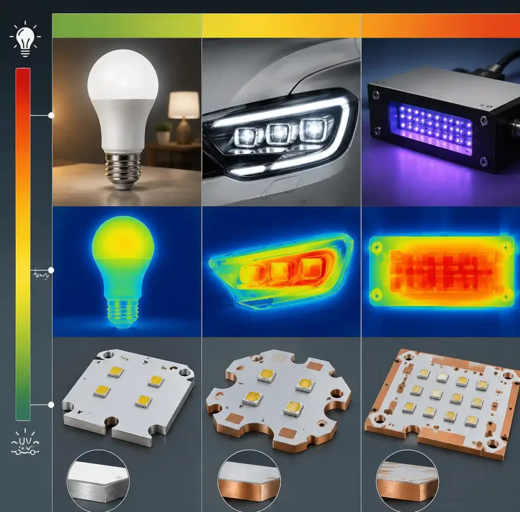
| LED bulbs, tubes, residential downlights | 1–5 W/in² | Standard aluminum PCB (1.0–2.0 W/m·K) | Cost minimization; T_j <100°C with passive cooling |
| Commercial downlights, troffers, panel lights | 5–10 W/in² | Standard to mid-range (1.5–3.0 W/m·K) | Balance cost and lifetime warranty |
| Automotive headlamps, daytime running lamps | 10–20 W/in² | High thermal aluminum PCB (3.0–5.0 W/m·K) | AEC-Q100; vibration; T_j <110°C |
| Industrial high-bay, stadium floodlights | 15–25 W/in² | High thermal aluminum PCB (4.0–6.0 W/m·K) | 50,000+ hour lifetime; thermal cycling |
| LED video walls, stage lighting | 20–35 W/in² | Ultra-high thermal aluminum or copper core | Compact form factor; forced air cooling |
| UV curing, horticultural grow lights | 30–50 W/in² | Copper core MCPCB (6.0–12.0 W/m·K) | Maximum power density; active cooling mandatory |
This assumes LED junction-to-case thermal resistance (R_th_jc) of 3–8 °C/W for mid-power LEDs and 1–3 °C/W for COB LEDs. The total junction-to-ambient path determines if your LED stays within its rated T_j maximum (typically 125–150°C).
Manufacturing and Design Rule Considerations
Aluminum PCBs and MCPCBs have different constraints than FR4. The metal core affects drilling, routing, and assembly.
Minimum trace width and spacing: Standard aluminum with 1 oz copper: 8 mils (0.2 mm) minimum. High thermal dielectrics are more brittle—sometimes 10 mil min to maintain yield. Copper core may require 12 mil min due to harder substrate drilling.
Via limitations: Through-hole vias can’t be used in single-layer aluminum PCBs—the metal core is conductive and would short everything. Thermal vias aren’t needed; the metal core is the thermal path.
Surface finish: ENIG is preferred for LED applications—excellent solderability and wire bonding. HASL is avoided due to the metal core’s high thermal mass causing uneven coating. OSP is used in cost-sensitive applications with short shelf life.
Thermal Design Calculation Example
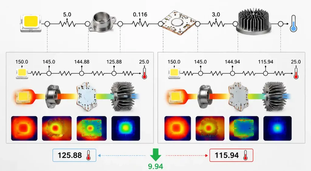
10W LED array with four 2.5W LEDs on a 2 × 2 inch board, R_th_jc of 5 °C/W per LED, heatsink R_th_sa of 3 °C/cm².
With standard aluminum PCB (3.0 °C·cm²/W):
- PCB thermal resistance: 3.0 ÷ 25.8 cm² = 0.116 °C/W per LED
- Total R_th_ja = 5 + 0.116 + 3 = 8.116 °C/W
- ΔT = 2.5W × 8.116 = 20.3°C
- At 40°C ambient, T_j = 60.3°C
With high thermal aluminum PCB (1.0 °C·cm²/W):
- PCB thermal resistance: 1.0 ÷ 25.8 = 0.039 °C/W per LED
- Total R_th_ja = 5 + 0.039 + 3 = 8.039 °C/W
- ΔT = 2.5W × 8.039 = 20.1°C
- T_j = 60.1°C
Modest improvement here because LED junction-to-case and heatsink dominate. For compact designs without external heatsinks or higher power densities, upgrading to high thermal aluminum can cut junction temperature by 10–20°C.
When to Choose Which Material
Standard aluminum (1.0–2.0 W/m·K):
- Power density below 5 W/in²
- External heatsink does the heavy lifting
- Cost is the dominant constraint
- Residential/commercial lighting
High thermal aluminum (3.0–6.0 W/m·K):
- Power density 10–25 W/in²
- Compact design limits heatsink size
- Extended warranty (5+ years) or automotive applications
- High ambient temperature (40–50°C)
Copper core MCPCB (6.0–12.0 W/m·K):
- Power density exceeds 30 W/in²
- Maximum thermal performance regardless of cost
- Weight not a constraint (fixed installation)
- UV LED curing, LED cinema projectors, concentrated PV
Hybrid stackups exist for multi-layer LED driver designs—FR4 layers on one side bonded to an aluminum core. Costs 2–3× more than standard aluminum but optimizes cost by using aluminum only where thermal performance is needed.
FAQ
How do I calculate the required thermal conductivity for my LED design?
Start with LED manufacturer’s R_th_jc, power dissipation per LED, and max allowable junction temperature. Subtract R_th_jc and heatsink R_th_sa from total thermal budget. Required PCB thermal resistance: R_th_pcb = (T_j_max – T_ambient) / P_dissipation – R_th_jc – R_th_sa. Convert to required dielectric thermal conductivity using dielectric thickness and board area.
Can I use aluminum PCB for multilayer LED driver circuits?
Yes, but with constraints. Standard aluminum PCBs are single-layer. For multilayer needs, use hybrid: FR4 multilayer stackup for the driver circuit bonded to an aluminum core, LED circuit layer on the bottom. This costs 2–3× more than standard aluminum.
Does aluminum PCB require special assembly processes?
Reflow profiles need to account for high thermal mass—preheat zones may need longer dwell or higher temperature. ENIG surface finish with SAC305 solder works well. Avoid wave soldering due to thermal shock risk.
What is the weight difference between aluminum and copper core PCBs?
Aluminum density 2.7 g/cm³ vs copper 8.9 g/cm³. For a 100 × 100 mm board with 1.5 mm core, aluminum weighs ~40g, copper ~130g. In automotive and aerospace, this 3× weight penalty makes copper core impractical unless absolutely necessary.
Conclusion
For LED designs in the 10–25 W/in² power density range—automotive headlamps, commercial high-bay lighting, outdoor floodlights—high thermal conductivity aluminum PCB with 4–6 W/m·K dielectric is the engineering sweet spot. It cuts junction temperature by 10–15°C compared to standard aluminum while keeping material costs manageable.
Before finalizing, validate your thermal calculations with the manufacturer’s actual thermal resistance test data (ASTM D5470 or equivalent), not just the dielectric thermal conductivity spec. A 0.5 °C·cm²/W difference in PCB thermal resistance translates to 5–10°C junction temperature difference in compact LED designs—directly affecting your lumen maintenance and field reliability. Partnering with a PCB manufacturer that has proven capability in aluminum and metal-core board fabrication ensures consistent thermal performance and manufacturing quality across production volumes.