
Motor Drive PCB Layout Guidelines
Introduction
Designing a printed circuit board (PCB) for motor drive applications presents unique challenges due to high currents, fast switching frequencies, and electromagnetic interference (EMI). A well-optimized PCB layout ensures reliable operation, thermal efficiency, and minimal noise. This guide provides key considerations and best practices for motor drive PCB design.
1. Understanding Motor Drive PCB Requirements
Motor drive circuits typically include:
- Microcontroller (MCU) or PWM Controller – Generates control signals.
- Gate Drivers – Amplifies PWM signals to drive power switches.
- Power Switches (MOSFETs/IGBTs) – Controls motor current.
- Current Sensing Circuitry – Monitors motor current for feedback control.
- Power Supply and Decoupling – Provides stable voltage rails.
Each component requires careful placement and routing to minimize parasitic effects, voltage drops, and EMI.
2. PCB Stackup and Layer Planning
A well-structured stackup improves signal integrity and power distribution. For motor drives:
- 4-Layer PCB (Recommended):
- Top Layer: High-frequency signals (PWM, gate drive signals).
- Inner Layer 1 (Ground Plane): Provides a low-impedance return path.
- Inner Layer 2 (Power Plane): Distributes motor and logic power.
- Bottom Layer: High-current power traces and heat dissipation.
- 2-Layer PCB (Budget Option):
- Top Layer: Signal and power routing.
- Bottom Layer: Ground plane with minimal splits.
Key Tips:
- Avoid splitting ground planes under high-current paths.
- Use thick copper (≥ 2 oz) for high-current traces.
3. Component Placement Strategies
3.1 Power Stage Placement
- Place MOSFETs/IGBTs close to the motor connector to minimize high-current loop area.
- Position gate drivers near the power switches to reduce parasitic inductance in gate drive paths.
- Keep decoupling capacitors as close as possible to power pins.
3.2 Signal and Control Section
- Group MCU, PWM generator, and feedback circuits away from high-power sections.
- Ensure analog signals (current sensing, encoder feedback) are routed away from noisy switching paths.
3.3 Thermal Considerations
- Use thermal vias under power components to dissipate heat.
- Provide adequate copper pours for heat spreading.
- Consider external heatsinks for high-power designs.
4. High-Current Routing Techniques
4.1 Trace Width and Current Capacity
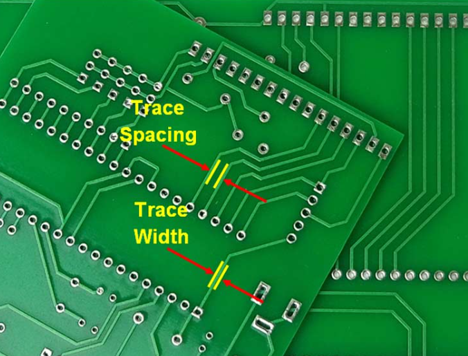
- Use trace width calculators (e.g., Saturn PCB Toolkit) to determine minimum widths.
- Example: For 10A current with 2 oz copper, a 5mm trace width may be required.
4.2 Minimizing Loop Inductance
- High di/dt switching causes voltage spikes if loop inductance is high.
- Keep high-current loops tight (e.g., MOSFET → Motor → Current Sense → Ground).
- Use parallel traces for very high currents.
4.3 Avoiding Ground Bounce
- Use a solid ground plane with minimal cuts.
- Separate analog and power grounds, connecting them at a single point.
5. Reducing EMI and Noise
5.1 Proper Decoupling
- Place 0.1µF ceramic capacitors near IC power pins.
- Use bulk capacitors (10µF–100µF) near power inputs.
5.2 Shielding and Filtering
- Use ferrite beads on motor leads to suppress high-frequency noise.
- Implement RC snubbers across MOSFETs to dampen ringing.
5.3 Signal Isolation
- Route sensitive analog signals (current sensing, feedback) differentially.
- Avoid running high-speed signals parallel to power traces.
6. Gate Drive Circuit Layout
6.1 Short Gate Drive Paths
- Keep gate drive traces short and wide (≥ 20 mils).
- Use twisted pairs or shielded cables for long gate drive connections.
6.2 Avoiding Cross-Talk
- Separate high-side and low-side gate drive traces.
- Use guard traces or ground shielding between critical signals.
7. Testing and Validation
Before finalizing the PCB:
- Simulate critical paths (e.g., power loops, gate drive signals) using SPICE or Ansys SIwave.
- Measure switching waveforms with an oscilloscope to check for overshoot/ringing.
- Thermal imaging helps identify hot spots under load.
8. Common Mistakes to Avoid
❌ Long high-current traces → Excessive voltage drop and heating.
❌ Poor ground return paths → EMI and unstable operation.
❌ Insufficient decoupling → Voltage spikes and MCU resets.
❌ Ignoring thermal management → Premature MOSFET failure.
Conclusion
A well-designed motor drive PCB ensures efficiency, reliability, and low noise. Key takeaways:
✔ Optimize layer stackup for power and signal integrity.
✔ Minimize high-current loop areas.
✔ Use proper decoupling and thermal management.
✔ Test thoroughly before mass production.
By following these guidelines, engineers can develop robust motor drive PCBs for applications like drones, robotics, and industrial automation.