
PCB for Underwater and Marine Applications: Waterproofing and Corrosion Protection
Marine electronics face some of the harshest operating conditions in the PCB industry. Saltwater exposure causes corrosion failures in unprotected boards within 6-12 months, while moisture ingress leads to electrical shorts and component degradation. Studies show that 35-40% of marine equipment failures trace back to PCB-related corrosion and water damage.
If you design electronics for underwater ROVs, marine instrumentation, or coastal equipment, you need to understand IP rating requirements, conformal coating versus potting methods, corrosion-resistant surface finishes, and salt spray testing standards. This guide provides actionable design strategies from ROV manufacturers and marine electronics engineers.
What Are Marine PCBs?
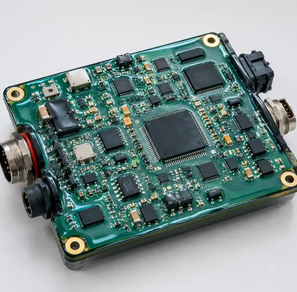
Marine PCBs are specialized circuit boards designed to withstand continuous saltwater exposure, high humidity, temperature cycling, and mechanical vibration in ocean environments. These boards operate in conditions ranging from splash zones on ship decks to full submersion at depth in autonomous underwater vehicles (AUVs).
According to IEC 60529 ingress protection standards, marine electronics require IP67 rating (submersion to 1 meter for 30 minutes) for deck-mounted equipment or IP68 rating (continuous submersion beyond 1 meter) for underwater applications. The PCB must resist galvanic corrosion from saltwater’s 3.5% sodium chloride content and maintain insulation resistance above 100 MΩ despite 80-95% relative humidity.
You can use rigid-flex PCB construction for marine applications because it eliminates connectors—the primary water ingress points—while providing flexibility for cable routing in compact enclosures.
Saltwater Corrosion Mechanisms and Prevention
Understanding Galvanic Corrosion
Saltwater acts as an electrolyte enabling galvanic corrosion between dissimilar metals on PCBs. Chloride ions (Cl⁻) penetrate protective layers and cause pitting corrosion on copper traces, increasing resistance and creating open circuits. The galvanic series shows copper anodes corrode when coupled with noble metals like gold through ionic saltwater paths.
Corrosion challenges in marine PCBs include electrochemical degradation accelerated by salt spray, moisture absorption causing delamination and electrical leakage, mixed metal components creating galvanic cells, and environmental cycling between wet and dry conditions that accelerates attack.
Research shows properly protected marine PCBs survive years of saltwater exposure, while unprotected boards fail within months despite seemingly robust construction.
Material Selection for Corrosion Resistance
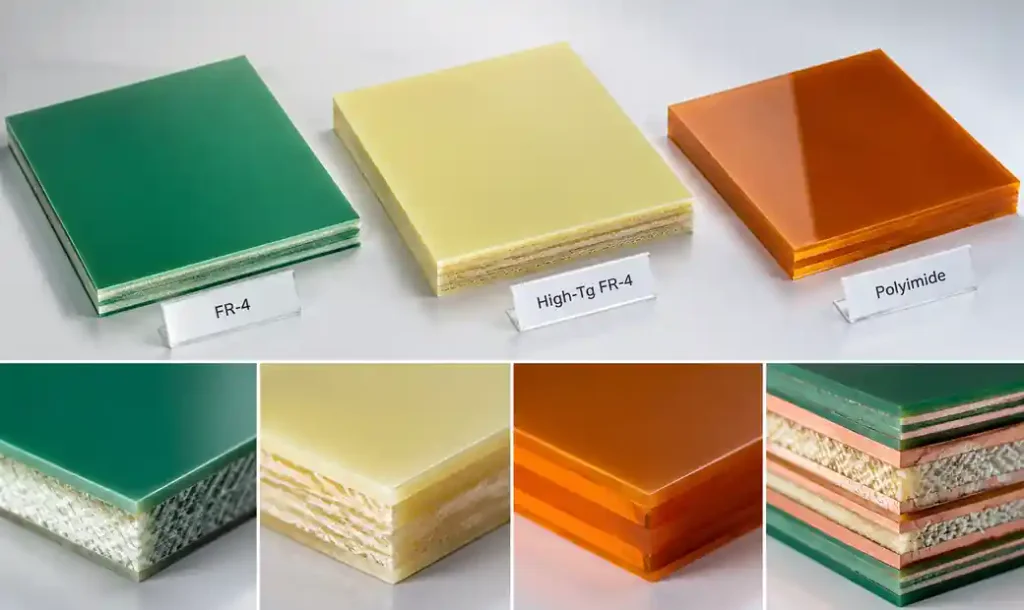
High-Tg FR-4 laminates with glass transition temperatures of 170-180°C provide better dimensional stability during temperature cycling from -20°C to +85°C typical in marine environments. Standard FR-4 (Tg 130-140°C) softens at elevated temperatures, allowing moisture penetration pathways.
Polyimide substrates offer superior chemical resistance to saltwater and maintain mechanical properties across -55°C to +250°C. Material properties including Tg and moisture absorption directly impact long-term reliability in humid marine conditions.
Specify 2oz (70µm) copper or heavier to increase trace cross-section and reduce vulnerability to pitting corrosion. Thicker copper maintains conductivity longer even as corrosion begins at edges and exposed areas.
| Material | Tg (°C) | Moisture Absorption | Chemical Resistance | Marine Suitability |
|---|---|---|---|---|
| Standard FR-4 | 130-140 | 0.10-0.15% | Fair | Limited to splash zones |
| High-Tg FR-4 | 170-180 | 0.08-0.12% | Good | General marine use |
| Polyimide | 250-280 | 0.24-0.40% | Excellent | Underwater submersion |
| Rogers RO4000 | 280+ | <0.06% | Excellent | High-reliability marine |
Surface Finish Selection for Marine Environments
ENIG and ENEPIG Comparison
ENIG (Electroless Nickel Immersion Gold) provides excellent corrosion resistance through a 3-6µm nickel barrier layer topped with 0.05-0.23µm immersion gold. The nickel protects copper from oxidation while gold prevents nickel surface oxidation and ensures long-term solderability.
ENEPIG surface finish technology adds a palladium layer (0.05-0.1µm) between nickel and gold, creating superior corrosion protection. The palladium barrier prevents galvanic corrosion between nickel and gold layers—a failure mode in harsh marine environments.
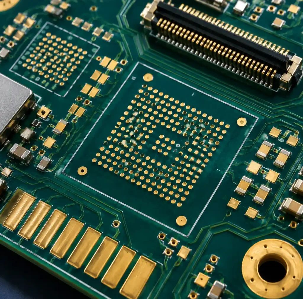
Testing shows ENEPIG withstands 1000+ hours salt spray testing per ASTM B117 without degradation, while ENIG may show nickel corrosion after 500-700 hours. For underwater electronics requiring extended submersion, specify ENEPIG to maximize lifespan.
Surface Finish Corrosion Resistance Data
| Finish Type | Layer Structure | Salt Spray Hours | Cost | Best For |
|---|---|---|---|---|
| HASL | Tin-lead | <100 hours | Lowest | Not recommended for marine |
| OSP | Organic coating | <200 hours | Low | Not suitable for marine |
| ENIG | Ni (3-6µm) + Au (0.05-0.23µm) | 500-700 hours | Moderate | Deck equipment, splash zones |
| ENEPIG | Ni + Pd + Au | 1000+ hours | High | Underwater, full submersion |
| Hard Gold | Ni + Au (0.75-2.5µm) | 1000+ hours | Highest | Connectors, wear surfaces |
Conformal Coating Technologies
Coating Material Comparison
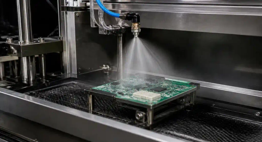
Conformal coatings create a 25-75µm protective barrier preventing moisture and salt contact with PCB surfaces. Material selection depends on chemical resistance, flexibility, thermal range, and reworkability requirements.
Acrylic coatings (AR) provide good moisture protection with easy rework using solvents. Dielectric strength reaches 1500V/mil with operating range -40°C to +125°C. Silicone coatings (SR) offer maximum flexibility and widest temperature range (-55°C to +200°C) with excellent stress relief during thermal cycling.
Polyurethane coatings (UR) deliver superior chemical and abrasion resistance with dielectric strength up to 2000V/mil. Parylene coating provides superior moisture barrier with thickness as low as 5-50µm penetrating into component crevices through vacuum deposition process.
For marine applications requiring IP67/IP68 ratings, conformal coating alone provides insufficient protection. You should combine coating with potting or hermetic enclosures to achieve submersion ratings.
Application Methods and Design Considerations
Spray coating covers large production volumes economically but may leave shadowed areas under components. Brush application provides localized protection for rework but lacks uniformity. Dip coating ensures complete coverage including component undersides—critical for marine reliability.
Parylene vapor deposition creates pinhole-free conformal barrier penetrating micro-gaps. This vacuum process coats all exposed surfaces uniformly including blind vias and component leads. Design keep-out areas around connectors and test points requiring electrical access.
Potting and Encapsulation Methods
Epoxy Potting for Maximum Protection
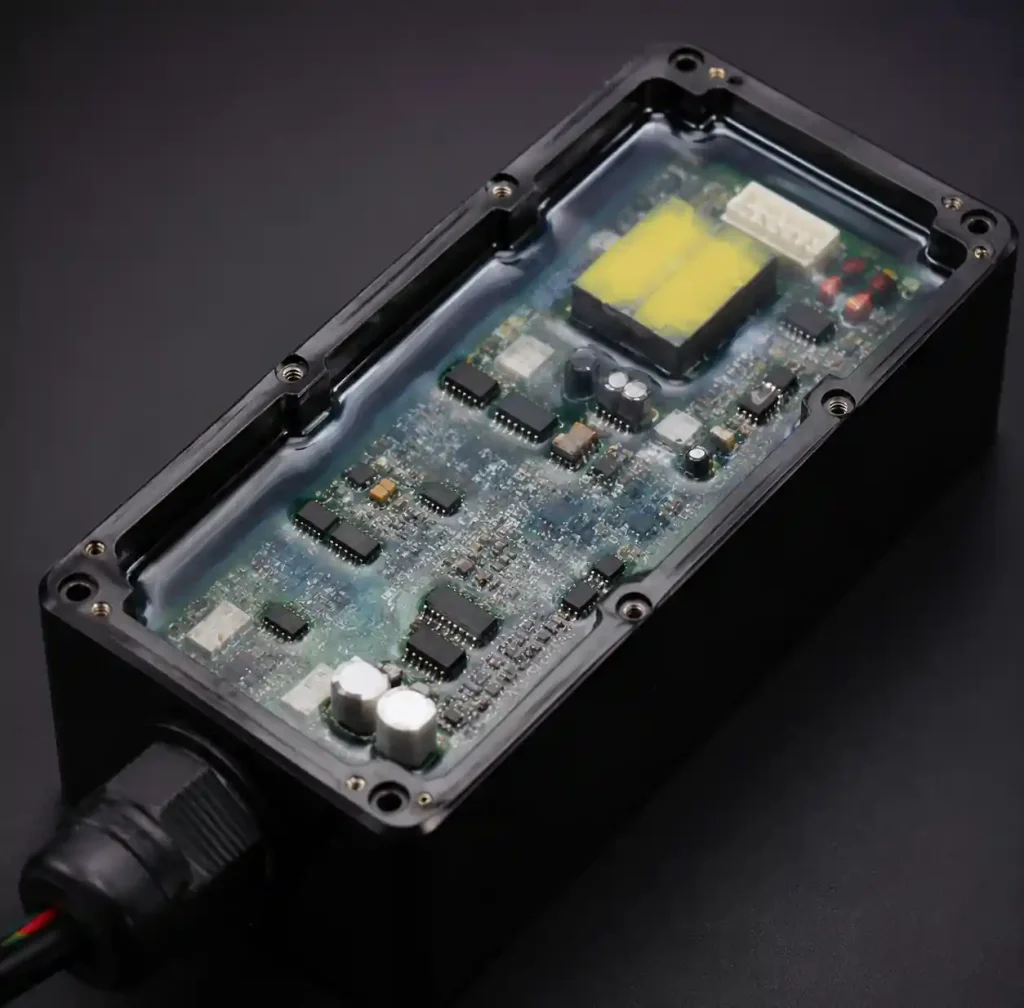
Epoxy potting compounds provide complete encapsulation creating a sealed mass protecting PCBs from water ingress, pressure, and mechanical shock. Two-part epoxies cure to Shore D hardness 75-85, effectively waterproofing the assembly.
Thermal conductivity ranges from 0.6 W/mK for standard formulations to 3 W/mK with ceramic or metal fillers. For power electronics requiring heat dissipation, specify thermally enhanced epoxy or design heat sinks extending outside potting compound.
Epoxy potting eliminates reworkability—components are permanently encased. This tradeoff is acceptable for marine applications where field reliability outweighs serviceability. Underwater ROV manufacturers pot complete electronics modules to achieve IP68 ratings for submersion to 100+ meters.
Polyurethane and Silicone Alternatives
Polyurethane encapsulants balance protection with rework capability at Shore A hardness 60-90. Material remains flexible, absorbing vibration from wave action and engine vibration. You can remove polyurethane mechanically or with chemical dissolution for component replacement.
Silicone potting compounds offer maximum flexibility (Shore A 20-60) and widest temperature range. Low modulus reduces mechanical stress on components during thermal cycling. Silicone maintains properties from -60°C to +200°C—ideal for extreme marine environments from Arctic to tropical waters.
IP Rating Requirements and Testing
IP67 vs IP68 for Marine Applications
IP ratings per IEC 60529 define dust and water ingress protection levels. The first digit (6) indicates complete dust protection—essential for marine environments with salt spray. The second digit defines water protection depth and duration.
IP67 certification requires submersion to 1 meter depth for 30 minutes without water ingress. This suits deck-mounted marine equipment, navigation displays, and splash-zone installations. IP68 extends protection to manufacturer-specified depths beyond 1 meter with continuous submersion.
Specify IP67 for boat electronics, fish finders, and marine instrumentation in protected enclosures. Specify IP68 with defined depth rating (typically 10-100 meters) for underwater cameras, ROV electronics, oceanographic sensors, and AUV control systems.
Critical design point: IP68 does not automatically include protection against spray jets or thermal shock. Testing gaps exist between ratings—verify complete test coverage for actual marine exposure conditions including pressure, temperature cycling, and mechanical shock.
Design for IP68 Sealing
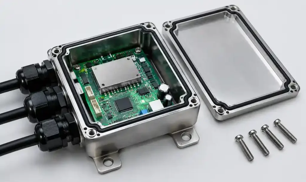
Hermetic enclosures use machined aluminum or stainless steel housings with O-ring seals. Design mating surfaces with O-ring grooves per ISO 3601 standards ensuring compression of 15-25%. Surface finish must be Ra 0.8µm or better to prevent seal leakage paths.
Cable penetrations require specialized glands with compression seals or overmolding. Each wire entry represents a potential failure point. ROV designs minimize penetrations through bulkhead connectors and custom sealing solutions.
Pressure compensation may be necessary for deep submersion preventing enclosure collapse. Vents with hydrophobic membranes equalize pressure while blocking water. Test assemblies to 1.5× maximum operating depth for safety margin.
Salt Spray Testing Standards
ASTM B117 and IEC 60068-2-52
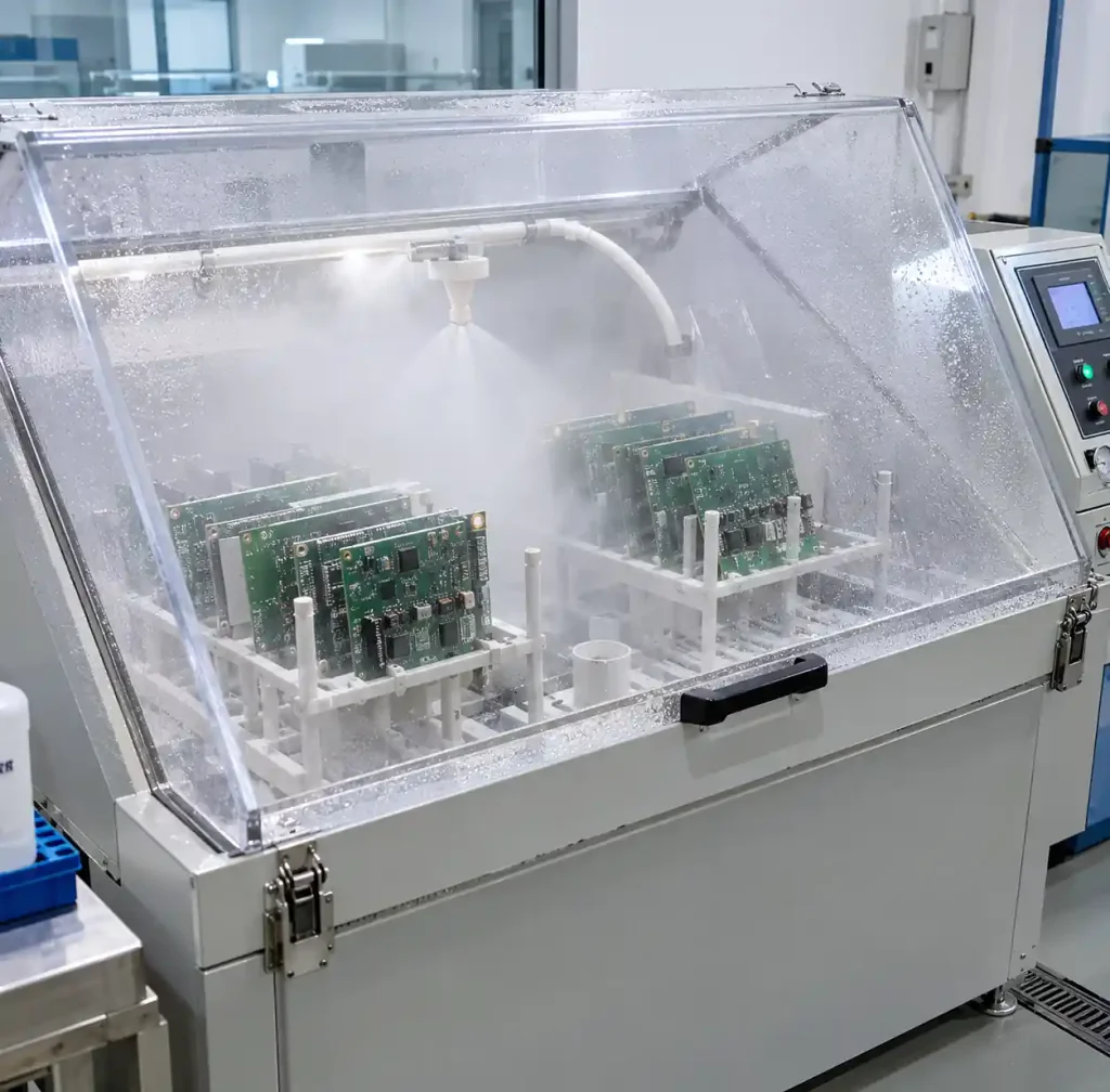
ASTM B117 salt spray testing is the most widely used accelerated corrosion test worldwide. Specimens are exposed to continuous 5% sodium chloride fog at 35°C, simulating years of marine exposure in weeks.
For marine electronics, 1000+ hours exposure demonstrates adequate corrosion resistance. Surface finishes, conformal coatings, and complete assemblies undergo testing to verify protection effectiveness. Visual inspection identifies rust, corrosion, blistering, or coating degradation.
IEC 60068-2-52 provides international salt mist testing standards with severity levels from 2 hours to 96+ hours depending on application. Method 1 uses 5% NaCl solution similar to ASTM B117. Method 2 adds acetic acid creating more aggressive conditions for accelerated testing.
Specify minimum 500-hour salt spray resistance for deck equipment and 1000+ hours for fully submerged electronics. Test complete assemblies including enclosures, not just bare PCBs, because system integration affects corrosion paths.
Design Guidelines for Marine PCBs
Layout and Component Placement
Space components minimum 1.5mm apart allowing conformal coating penetration between parts. Avoid trapped voids where moisture accumulates. Orient components to prevent water pooling on top surfaces after submersion.
Route traces with 10-15 mil spacing minimum preventing salt crystal bridging during wet-dry cycles. Increase clearances around high-voltage traces to maintain insulation resistance above 100 MΩ in humid conditions. Use filled vias preventing capillary wicking of moisture through board thickness.
Design mounting holes 5mm from board edges with plated through-holes adding mechanical strength. Apply soldermask over exposed copper areas—exposed copper corrodes rapidly in saltwater. Specify soldermask dams between fine-pitch pads preventing solder bridging and reducing moisture paths.
Connector Strategy and Strain Relief
Connectors are the weakest point in marine PCB systems. Each mating interface risks water ingress and galvanic corrosion. Minimize connector count through rigid-flex integration eliminating cable assemblies.
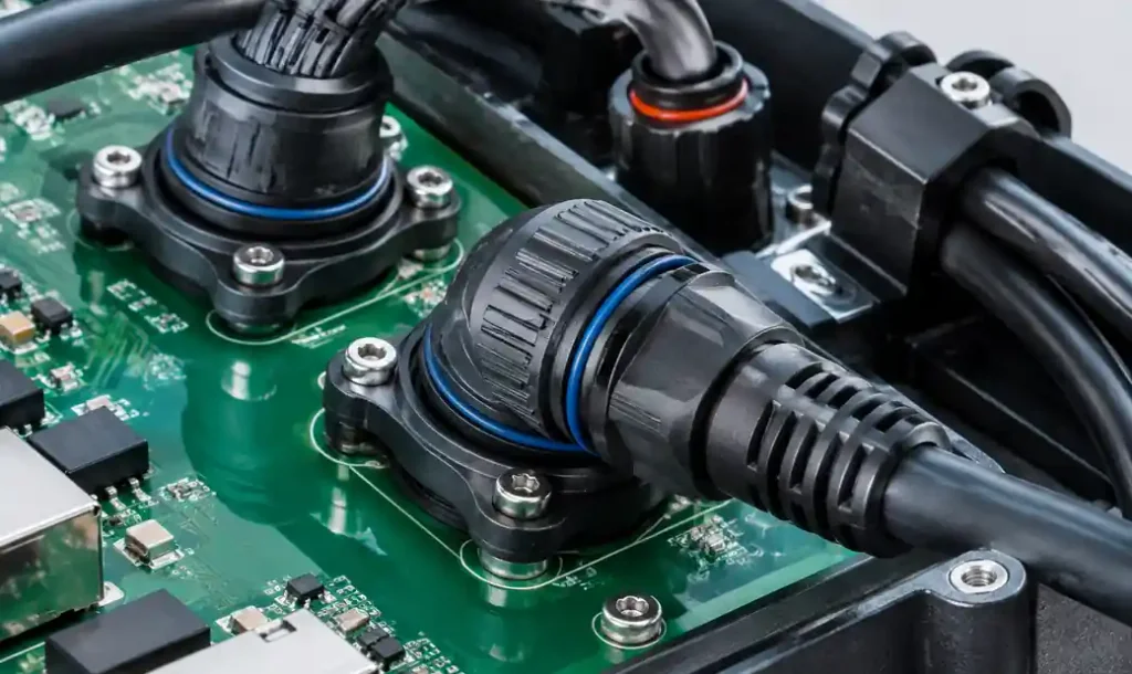
When connectors are necessary, specify marine-grade types with gold-plated contacts and O-ring seals. Bulkhead-mount connectors extend through enclosure walls with compression sealing. Apply strain relief preventing cable tension from stressing solder joints during wave action or vehicle movement.
Design connector keep-out zones for potting—mask areas requiring electrical access. Use conformal coating around connector solder joints as first-line defense before final potting.
Manufacturing and Assembly Considerations
PCB Fabrication Requirements
Specify IPC-6012 Class 3 requirements for marine electronics requiring extended reliability. Class 3 mandates tighter tolerances, increased inspection, and electrical testing ensuring no latent defects that could fail in harsh environments.
Require 100% electrical testing at 250V minimum to verify insulation resistance. Specify controlled impedance testing for high-speed communication circuits. Order impedance coupons for verification per IPC-TM-650 test methods.
Copper thickness should be 2oz (70µm) minimum for marine applications. Heavier copper increases corrosion resistance and current carrying capacity for power distribution. Specify filled vias preventing moisture wicking through via barrels.
Assembly Process Controls
Bake moisture-sensitive components per J-STD-033 before reflow preventing popcorning during high-temperature processing. Use nitrogen reflow with oxygen below 100 ppm reducing oxidation and improving solder joint reliability.
Clean assemblies with deionized water removing flux residues and ionic contaminants that accelerate corrosion. Ionic cleanliness testing should achieve <1.56 µg/cm² NaCl equivalent per IPC-TM-650 method 2.3.25. Residual flux under conformal coating creates corrosion cells in humid marine environments.
Apply conformal coating within 4 hours after cleaning preventing moisture absorption. Cure coatings per manufacturer specifications ensuring complete polymerization. Perform electrical testing after coating verifying no defects or contamination affecting functionality.
Frequently Asked Questions
What is the difference between IP67 and IP68 ratings for marine PCBs?
IP67 provides protection against submersion to 1 meter depth for 30 minutes, suitable for deck equipment and splash zones. IP68 offers protection for continuous submersion beyond 1 meter at manufacturer-specified depths, required for underwater ROVs, AUVs, and oceanographic instruments. Both provide complete dust protection (first digit 6), but IP68 demands hermetic sealing and pressure testing to deeper ratings.
Should I use conformal coating or potting for marine electronics?
Conformal coating (25-75µm) provides 80% protection with full rework capability, suitable for service-accessible equipment in splash zones. Potting (3-10mm encapsulation) provides 100% protection achieving IP68 ratings but eliminates rework. For underwater submersion applications, potting is required. For deck equipment requiring occasional service, combine conformal coating with sealed enclosures achieving IP67 without permanent encapsulation.
Which surface finish provides best corrosion resistance in saltwater?
ENEPIG (Electroless Nickel Electroless Palladium Immersion Gold) offers superior saltwater corrosion resistance withstanding 1000+ hours salt spray testing. The palladium barrier prevents galvanic corrosion between nickel and gold layers. ENIG provides good protection (500-700 hours) at lower cost for less demanding marine applications. Avoid HASL and OSP finishes for marine use—both corrode rapidly in saltwater environments.
How long should marine PCBs withstand salt spray testing?
Specify minimum 500-hour ASTM B117 salt spray resistance for deck-mounted equipment in splash zones. Underwater electronics requiring continuous submersion should achieve 1000+ hours without corrosion. Test complete assemblies including conformal coating, potting, and enclosures—bare PCB testing alone does not validate system-level protection. IEC 60068-2-52 provides international salt mist standards for marine qualification.
What materials work best for underwater PCB applications?
High-Tg FR-4 (Tg 170-180°C) provides good baseline performance for general marine use. Polyimide substrates offer superior chemical resistance and temperature stability for demanding underwater applications. Specify 2oz copper minimum for corrosion resistance and ENEPIG surface finish for extended saltwater exposure. Rogers high-frequency laminates provide lowest moisture absorption (<0.06%) for critical high-reliability applications requiring decades of submersion.
Conclusion
PCB design for underwater and marine applications demands comprehensive protection strategies addressing saltwater corrosion, moisture ingress, and pressure exposure. Success requires proper material selection including high-Tg laminates and ENEPIG surface finish, protection methods combining conformal coating with potting or hermetic sealing, IP67/IP68 rating verification through testing, and salt spray qualification per ASTM B117 demonstrating 500-1000+ hour resistance.
Marine electronics must withstand conditions that destroy standard PCBs within months. Implementing these waterproofing and corrosion protection techniques from design phase through manufacturing ensures reliable operation for 5-15 years in harsh ocean environments.
Andwin Circuits manufactures marine-grade PCBs with high-Tg materials, ENEPIG surface finish, and conformal coating services. Our facility produces multilayer boards up to 50 layers with IPC-6012 Class 3 qualification and complete testing per IPC standards. We support rigid-flex PCB manufacturing eliminating connectors for maximum water resistance in underwater applications. Contact us for marine PCB solutions with factory-direct pricing and fast delivery in 7-15 days.