
PCB Warpage: Causes, Measurement, and Effective Repair Techniques
Abstract
Printed Circuit Board (PCB) warpage is a common issue in electronics manufacturing that can lead to significant production challenges and reliability concerns. This comprehensive article explores the root causes of PCB warpage, precise measurement techniques, and proven repair methods. By understanding the material science behind warpage and implementing appropriate corrective measures, manufacturers can improve yield rates, enhance product reliability, and reduce costly rework.
1. Introduction to PCB Warpage
PCB warpage refers to the undesired bending or twisting of circuit boards that typically occurs during manufacturing processes or in field operation. In an industry where component miniaturization and high-density interconnects have become standard, even minor warpage can cause serious assembly defects and long-term reliability issues.
The increasing complexity of modern PCBs—with multiple layers, mixed materials, and varying coefficient of thermal expansion (CTE) characteristics—has made warpage control more challenging than ever. Industry surveys indicate that PCB warpage accounts for approximately 15-20% of surface mount technology (SMT) assembly defects, making it a critical quality concern for electronics manufacturers.
2. Root Causes of PCB Warpage
2.1 Material-Related Causes
- Uneven Copper Distribution: Asymmetric copper patterns between layers create imbalanced internal stresses
- CTE Mismatch: Differences in thermal expansion coefficients between PCB materials (FR-4, polyimide, etc.) and copper
- Moisture Absorption: Hygroscopic properties of substrate materials leading to dimensional changes
- Resin System Characteristics: Cure shrinkage and post-cure behavior of epoxy resins
2.2 Process-Induced Warpage
- Lamination Process: Improper pressure and temperature profiles during multilayer bonding
- Thermal Cycling: Repeated exposure to high temperatures during soldering and rework
- Cooling Rate: Non-uniform cooling after high-temperature processes
- Mechanical Stress: Handling and fixture-related stresses during manufacturing
2.3 Design-Related Factors
- Asymmetric Stackup: Uneven layer distribution in multilayer boards
- Large Copper Areas: Imbalanced copper density across layers
- Mixed Material Boards: Combining materials with different mechanical properties
- Thin Core Materials: Insufficient stiffness in high-layer count boards

3. Warpage Measurement Techniques
Accurate quantification of PCB warpage is essential for process control and repair decisions. Common measurement methods include:
3.1 Shadow Moiré Technique
- Non-contact optical method using interference patterns
- Provides full-field warpage mapping with micron-level resolution
- Ideal for measuring dynamic warpage during thermal cycling
3.2 Laser Scanning
- High-precision 3D surface profiling
- Suitable for both bare boards and assembled PCBs
- Typical accuracy: ±5 μm
3.3 Coordinate Measuring Machines (CMM)
- Contact-based measurement with precision probes
- Excellent for localized warpage assessment
- Slower but highly accurate for critical measurements
3.4 Industrial Computed Tomography (CT)
- X-ray based 3D imaging of assembled boards
- Capable of measuring warpage under components
- Expensive but provides unparalleled internal structure data
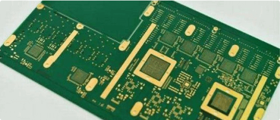
4. PCB Warpage Repair Methods
4.1 Thermal Straightening Techniques
4.1.1 Controlled Heating and Weighting
- Process:
- Place warped PCB on flat ceramic surface
- Apply evenly distributed weights (typically 0.5-2 psi)
- Gradually heat to 5-10°C above Tg (glass transition temperature)
- Maintain temperature for 30-90 minutes
- Slow cool at 1-2°C/minute under pressure
- Considerations:
- Requires precise temperature control
- Multiple cycles may be needed for severe warpage
- Risk of material degradation with excessive heating
4.1.2 Thermal Cycling with Constraint Fixtures
- Uses specialized aluminum or invar fixtures to constrain boards during heating
- Effective for warpage caused by CTE mismatch
- Typical cycle: 3-5 heating/cooling cycles between 25°C and 180°C
4.2 Mechanical Straightening Methods
4.2.1 Press Straightening
- Cold working process for minor warpage (<1% of diagonal length)
- Requires precision calibrated presses with protective layers
- Risk of microcracks in brittle materials
4.2.2 Roller Leveling
- Progressive straightening through series of precision rollers
- Suitable for thin PCBs (≤1.0mm)
- May affect surface finish quality
4.3 Hybrid Repair Approaches
4.3.1 Moisture Baking and Thermal Treatment
- Combination process for moisture-induced warpage:
- Pre-bake at 105-125°C for 2-4 hours to remove moisture
- Immediate thermal straightening while dry
4.3.2 Stress Relief Annealing
- Extended low-temperature bake (below Tg) for stress redistribution
- Typical parameters: 120-140°C for 4-8 hours
- Particularly effective for polyimide and high-Tg materials
5. Advanced Repair Techniques for Assembled Boards
5.1 Localized Heating with Component Protection
- Use of focused IR heaters or hot gas nozzles
- Thermal shields for sensitive components
- Real-time warpage monitoring during repair
5.2 Adhesive Reinforcement
- Application of low-CTE underfill or corner adhesives
- Selective stiffening of critical areas
- Compatible with rework processes
5.3 Structural Modification
- Strategic removal of copper in non-critical areas
- Addition of balancing copper patches
- Requires careful simulation to avoid new stress points
6. Warpage Prevention Strategies
6.1 Design Guidelines
- Maintain symmetrical copper distribution (≤10% density variation)
- Use balanced stackup with even layer counts
- Incorporate warpage relief features (stress relief slots, corner radii)
6.2 Material Selection
- High-Tg materials for improved thermal stability
- Low-CTE cores for large boards
- Moisture-resistant prepregs for humid environments
6.3 Process Controls
- Optimized lamination profiles with controlled ramp rates
- Proper storage conditions (25°C/30% RH recommended)
- Pre-baking before high-temperature processes
7. Industry Standards and Acceptance Criteria
- IPC-6012: Defines maximum allowable warpage (typically 0.75-1.0% of diagonal)
- J-STD-003: Soldering performance requirements accounting for warpage
- IPC-TM-650: Standard test methods for warpage measurement
8. Conclusion
PCB warpage repair requires a systematic approach combining material science knowledge, precise measurement, and controlled repair techniques. While thermal straightening remains the most common repair method, emerging technologies like localized stress relief and advanced fixture designs continue to improve repair success rates.
Effective warpage management must begin at the design stage and continue through all manufacturing processes. By implementing robust prevention strategies and having proven repair methods available, manufacturers can significantly reduce warpage-related defects and improve overall product quality.
Future developments in warpage control include smart materials with self-correcting properties, real-time warpage monitoring systems, and AI-driven process optimization tools that predict and prevent warpage before it occurs.