Rigid-Flex PCB Cost Reduction: 5 Proven Strategies to Cut Procurement Costs by 30% (2026)
This guide provides five proven strategies to reduce rigid-flex PCB costs by up to 30% while maintaining design integrity. Based on CAM engineering and DFM best practices, these recommendations help engineers and procurement managers optimize designs for cost-effective manufacturing.
Cut Flex Layer Count — Not All Layers Need to Bend
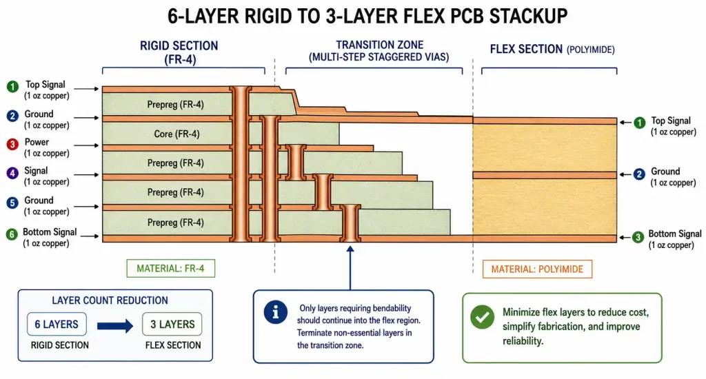
Layer count in the flex region is the biggest cost driver. Every extra layer increases material, lamination, and processing costs exponentially.
- Review each layer: If your 6-layer rigid board only needs 2 signal + ground in flex, reduce to 3 layers — saving 20–25%.
- Consolidate flex regions: Merge multiple short flex sections into one longer region — saving 10–15%.
- Use staggered vias in rigid sections (not through-vias in flex) — saves 8–12% and improves reliability.
- Allow larger bend radius: Standard 10× thickness; specifying 15× or 20× reduces tooling costs by 5–8%.
| Design Parameter | Standard Approach | Cost-Optimized | Cost Reduction |
|---|---|---|---|
| Flex layers | 6 layers through flex | 3 layers in flex region | 20–25% |
| Flex regions | 3 separate sections | 1 consolidated region | 10–15% |
| Via structure | Through-vias in flex | Staggered vias in rigid sections | 8–12% |
| Bend radius | 10× thickness | 15× thickness or higher | 5–8% |
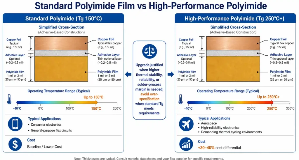
Choose Standard Materials — Upgrade Only When Necessary
Many designs over-specify materials. Standard grades often meet functional requirements at far lower cost.
- Flex polyimide: Standard 1–2 mil film works below 150°C. High-Tg (>250°C) costs 30–40% more — reserve for aerospace or multiple reflow passes.
- Rigid section: Use FR-4 Tg 130°C unless sustained >130°C requires high-Tg FR-4.
- Adhesive vs adhesiveless: Adhesive-based is fine for static or <1,000 cycles. Adhesiveless (+25–35%) only needed for >100,000 dynamic flexes.
- Copper weight: 1 oz is cheaper and easier than ½ oz — saves 10–15%.
📘 For high-reliability (IPC-6013 Class 3) applications like aerospace radar, see our Aerospace Radar Rigid-Flex PCB Design Guide for detailed material comparisons.
Relax Tolerances to Match Manufacturer Standard Capabilities
Tight tolerances drive up cost through premium equipment, extra inspection, and lower yields.
- Trace width/spacing: Move from 4/4 mil to 5/5 mil — saves 12–18%.
- Annular ring: IPC Class 2 (2 mil) vs Class 3 (4 mil) saves 8–12% if not required.
- Drill sizes: Limit to 3–5 standard diameters (0.3, 0.4, 0.5, 0.6, 0.8 mm) — saves 5–10%.
- Surface finish: ENIG with 2–3 µin gold (vs 5 µin) saves 6–10%; Immersion Silver or OSP saves 15–25% less than ENIG.
- Thickness tolerance: Allow ±15% instead of ±10% — saves 5–8%.
| Specification | Tight Tolerance | Relaxed (Standard) | Cost Impact |
|---|---|---|---|
| Trace width/spacing | 3/3 mil | 5/5 mil | 12–18% reduction |
| Annular ring | Class 3 (4 mil) | Class 2 (2 mil) | 8–12% reduction |
| Drill sizes | 8+ unique | 3–5 standard | 5–10% reduction |
| Gold thickness (ENIG) | 5 µin | 2–3 µin | 6–10% reduction |
| Overall thickness | ±10% | ±15% | 5–8% reduction |
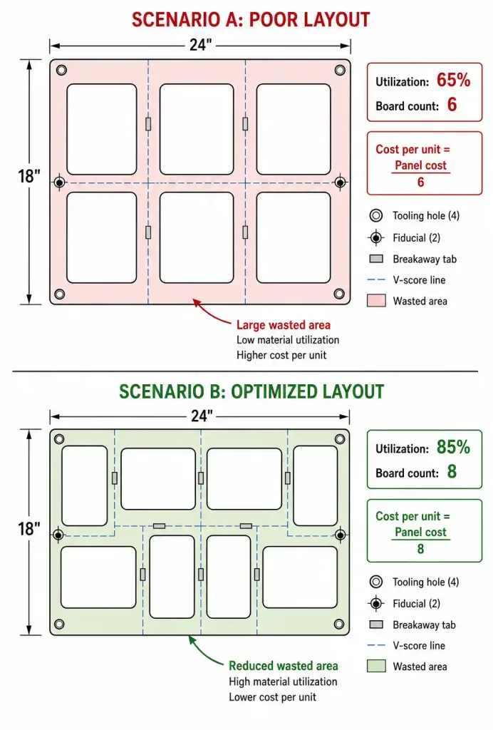
Optimize Panelization and Order Volume
High setup costs make panel utilization and order quantity critical.
- Panel utilization: Aim for 80–85% (vs 60–70%) — reduces per-unit cost by 10–15%. Work with CAM engineer on rotation and spacing.
- Increase prototype quantity: Going from 10 to 50 units amortizes NRE, cutting per-unit cost by 30–40%.
- Multi-project shared panel: Some manufacturers pool designs — saves 30–40% on prototypes (adds 1–2 weeks lead time).
- Engage volume supplier early: If scaling to 500+ units/year, commit early for 15–20% prototype discount and design feedback.
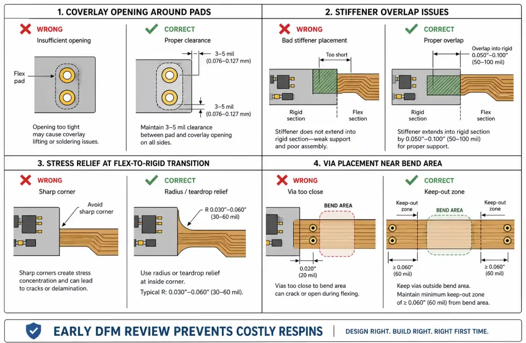
Partner with DFM-Capable Suppliers Early
Most costly mistakes happen during design. Involve your supplier before final layout.
- Request DFM review to catch coverlay, stiffener, transition, or stress issues — avoids expensive respins.
- Match design to supplier’s sweet spot (e.g., high-layer vs high-volume) — saves 15–25%.
- Use supplier design guidelines and stackup templates — reduces queries and yield loss.
- RFQ at least 3 suppliers — price differences of 20–40% are common.
- Consolidate with 1–2 preferred suppliers for 10–15% relationship discounts and priority support.
🔧 Supplier qualification is key. Our 10 Essential Qualifications to Audit When Choosing a Rigid-Flex PCB Supplier covers IPC certs, capabilities, traceability, and DFM processes.
FAQ
Q: When does rigid-flex beat rigid + connectors on total cost?
A: At >500 units/year in space-constrained or high-reliability designs, rigid-flex eliminates connectors, assembly labor, and failure points — often achieving lower system cost.
Q: IPC Class 2 or Class 3?
A: Class 2 for most consumer/industrial (saves 15–25%). Class 3 only for medical, aerospace, military where continued performance is critical.
Q: What minimum bend radius should I specify?
A: Standard 10× total flex thickness. Specifying 15× or 20× when feasible reduces cost and improves reliability.
🛡️ For harsh environments, conformal coating adds protection. See our Conformal Coating Material Selection Guide for acrylic, silicone, urethane, and epoxy comparisons.
Conclusion: Cost Optimization Checklist
Before ordering, ask:
- Can flex layer count be reduced?
- Are material grades justified by actual conditions?
- Are tolerances tighter than needed?
- Is panel utilization >80%?
By applying these five strategies, you can achieve 30% procurement cost savings while maintaining design integrity and manufacturability.
Further Reading:
- Aerospace Radar Rigid-Flex PCB Design (IPC-6013 Class 3)
- 10 Essential Qualifications for Rigid-Flex PCB Supplier
- How to Select Conformal Coating Material
All links are provided as additional resources. For specific applications, consult your PCB manufacturer or CAM team.