
Rigid Flex PCB vs Traditional PCB: Which is Right for Your Product?
Rigid flex PCB technology accounts for approximately 15% of the global PCB market, with demand growing at 11% annually through 2028. Despite higher initial costs, rigid flex circuits eliminate up to 60% of interconnects and reduce assembly failures by 40% compared to traditional rigid PCB designs with cable assemblies. This guide compares rigid flex versus traditional rigid PCB across design, cost, reliability, and applications to help you choose the right technology for wearables, medical devices, aerospace, and other demanding electronics.
What is Rigid Flex PCB?
Rigid flex PCB is a hybrid circuit board combining rigid sections with flexible layers in a single integrated assembly. Rigid sections support components while flexible sections bend and fold, eliminating connectors and cables between boards.
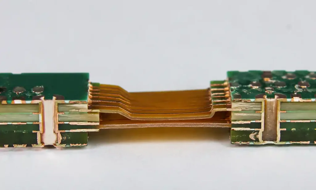
The flexible layers use polyimide substrate with rolled-annealed copper for repeated flexing. Rigid sections use FR4 or high-Tg materials. Rigid flex circuits support 2 to 20+ layers, providing superior reliability by eliminating connector interfaces that fail in vibration and shock environments.
What is Traditional Rigid PCB?
Traditional rigid PCB uses FR4 substrate in fixed flat configurations, from single-layer to complex multilayer stackups with up to 50 layers for high-density applications.
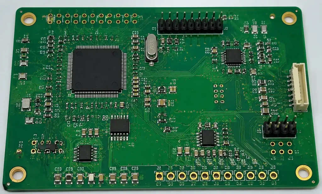
Rigid PCBs provide dimensional stability, cost-effectiveness for high volumes, and support heavy components. Traditional rigid boards connect through cables and connectors, offering modularity but introducing potential failure points at each interconnection.
Key Differences: Rigid Flex vs Traditional PCB
| Feature | Rigid Flex PCB | Traditional Rigid PCB |
|---|---|---|
| Construction | Integrated rigid and flexible layers | Rigid FR4 layers only |
| Interconnections | Eliminates 60-90% of connectors | Requires cables and connectors |
| Assembly Complexity | Single integrated unit | Multiple boards with cable assembly |
| Bend Capability | Flex sections support dynamic or static bending | No flexibility |
| Reliability (MTBF) | 40% fewer failure points | Higher failure risk at connectors |
| Weight | 30-50% lighter (no cables/connectors) | Heavier with cable assemblies |
| 3D Packaging | Supports complex 3D configurations | Limited to 2D or stacked arrangements |
| Cost per Unit | 2-5× higher for low volumes | Lower for high volumes |
| Lead Time | 15-25 days typical | 7-15 days typical |
| Design Complexity | Requires specialized flex design rules | Standard PCB design rules |
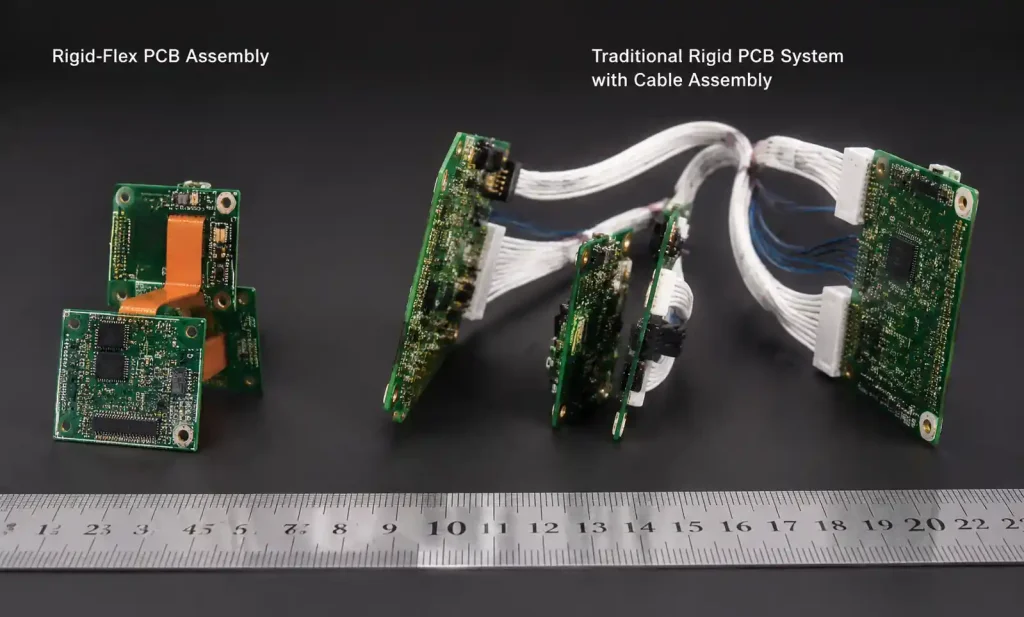
The fundamental difference lies in system architecture. Rigid flex integrates multiple rigid boards and interconnects into one assembly, reducing part count and improving reliability but requiring upfront investment in complex design and manufacturing.
Traditional rigid PCB excels in cost-sensitive, high-volume applications where boards remain stationary. Rigid flex becomes cost-effective when you factor in reduced assembly labor, higher reliability, and smaller product size.
Cost Comparison Analysis
The cost equation for rigid flex versus traditional rigid PCB extends beyond initial board fabrication. While rigid flex circuits cost 2-5× more per board, total system cost often favors rigid flex for compact, high-reliability products.
| Cost Factor | Rigid Flex PCB | Traditional Rigid PCB + Cables |
|---|---|---|
| PCB Fabrication (per unit, 100 qty) | $80-$250 | $30-$80 (multiple boards) |
| Connectors & Cables | $0 (eliminated) | $15-$50 per interconnection |
| Assembly Labor | Lower (single unit) | Higher (cable routing, connector assembly) |
| Testing Time | Faster (fewer interconnects) | Slower (test each connection) |
| Failure Rate | 0.5-1% typical | 2-4% typical (connector-related) |
| Total System Cost (1000 units) | Often 15-30% lower | Higher with cables and assembly |
For volumes below 10,000 units annually, rigid flex often achieves lower total cost despite higher PCB fabrication costs. Savings come from reduced assembly time, lower failure rates, and smaller enclosures. Medical device manufacturers report 20-35% reduction in manufacturing costs when switching from multi-board rigid systems to integrated rigid flex designs.
Reliability and Performance Advantages
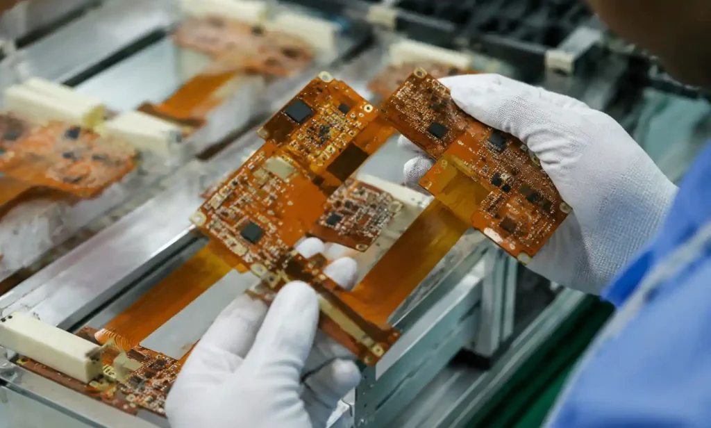
Rigid flex PCB delivers superior reliability by eliminating connectors and solder joints that fail in vibration and shock environments.
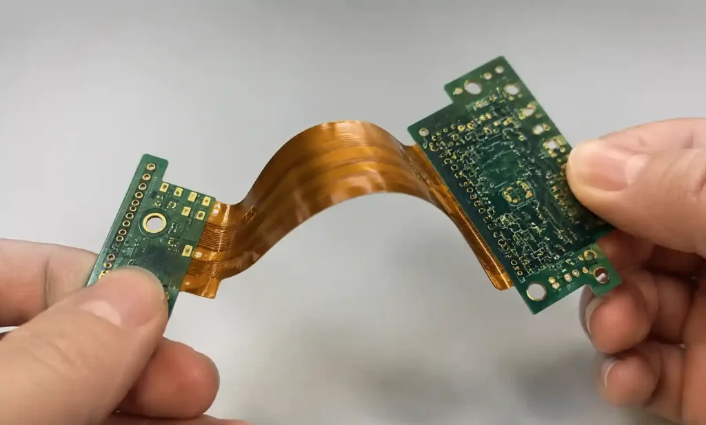
Key Reliability Improvements:
- MTBF: 40-60% higher than connector-based assemblies
- Vibration Resistance: Flex absorbs stress that fractures solder joints
- Signal Integrity: Eliminates connector discontinuities for high-speed signals
- Flex Life: 100,000+ cycles in dynamic applications
In aerospace and medical applications, rigid flex shows 3-5× lower failure rates under MIL-STD-810 testing. Controlled impedance maintains signal quality through bend areas.
Design Considerations
Designing rigid flex PCB requires specific design rules for flexible sections that differ from traditional rigid PCB guidelines.
Bend Radius Requirements:
- Static Bend: Minimum 6× total flex thickness
- Dynamic Flex: Minimum 10-20× total flex thickness
- Example: 0.2mm flex thickness requires 2mm static, 4mm dynamic bend radius
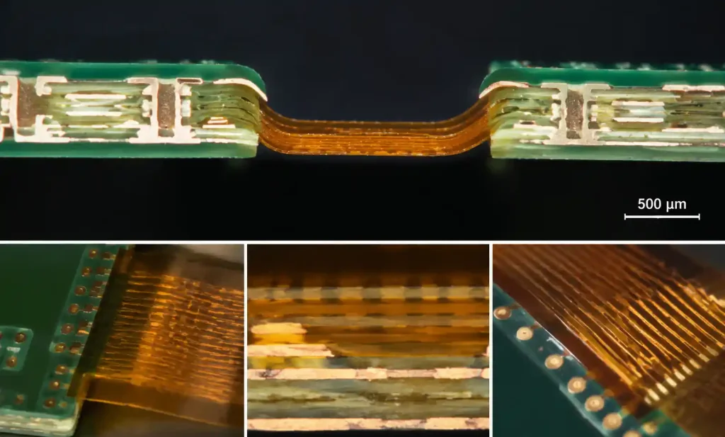
Critical Design Rules:
- Use rolled-annealed copper in flex regions (0.5-1oz max for dynamic flex)
- Route traces perpendicular to bend axis
- Specify 1-4 copper layers in flex sections
- Use coverlay instead of solder mask on flex areas
- Add stiffeners where connectors mount
- Maintain 8mil minimum trace width/spacing
Andwin Circuits provides design review services to optimize rigid flex manufacturability.
Application Suitability Guide
Ideal Rigid Flex PCB Applications:
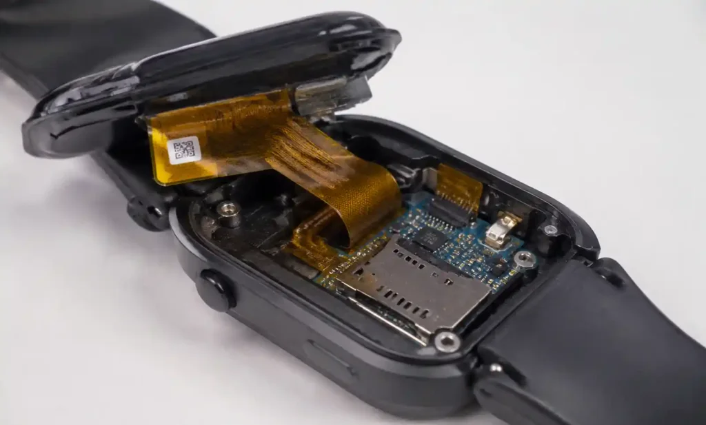
Wearable Devices: Smartwatches, fitness trackers, and AR/VR headsets require circuits conforming to curved enclosures. Rigid flex eliminates cable bulk while providing 30-50% thinner profiles.
Medical Devices: Implantable devices, surgical instruments, and patient monitors demand maximum reliability with minimal size. Medical equipment benefits from circuits conforming to anatomical requirements without connector failures during sterilization.
Aerospace and Defense: Avionics and satellite electronics withstand extreme vibration while minimizing weight. MIL-STD-810 qualified rigid flex delivers proven reliability.
Ideal Traditional Rigid PCB Applications:
Consumer Electronics: Smartphones and tablets use rigid PCB where automated assembly at millions of units drives cost optimization.
Industrial Control: PLCs and motor drives use robust rigid PCBs with through-hole components for field service.
Power Electronics: High-current supplies require thick copper (3-6oz) and heavy components that rigid PCB supports better than flex.

When to Choose Rigid Flex PCB
Select rigid flex PCB when your application meets three or more criteria:
- Space Constraints: Enclosure cannot accommodate cable routing
- 3D Packaging: Circuit must fold or conform to non-planar surfaces
- Reliability Critical: Cannot tolerate connector failures (medical, aerospace)
- Dynamic Flexing: Circuit flexes repeatedly during operation
- Weight Sensitive: Every gram matters (wearables, drones, aerospace)
- Harsh Environments: Extreme vibration, shock, or thermal cycling
- Assembly Simplification: Reducing assembly steps justifies higher PCB cost
Cost-Benefit Breakeven: Rigid flex becomes cost-effective when production is below 50,000 units annually AND assembly savings offset higher PCB costs, or when field failure costs exceed 2× the PCB cost difference.
When to Choose Traditional Rigid PCB
Choose traditional rigid PCB when:
- High Volume: Manufacturing exceeds 100,000 units annually
- Cost Sensitive: Margin does not support 2-5× higher PCB costs
- Design Modularity: System benefits from separate, replaceable modules
- Heavy Components: Requires thick copper (>2oz) or heavy heat sinks
- Rapid Prototyping: Need 7-10 day turnaround vs 20-25 days for rigid flex
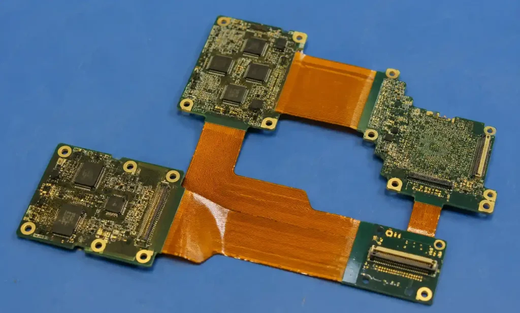
Hybrid Approach: Use flexible PCB for critical interconnections while using rigid-to-rigid connectors for non-critical links. For high layer counts (12-30 layers), traditional HDI PCB with microvias achieves density approaching rigid flex at lower cost.
FAQs
What is the main advantage of rigid flex PCB over traditional PCB?
Rigid flex eliminates connectors and cables by integrating rigid and flexible sections into one board. This reduces failure points by 60-90%, improves reliability, reduces weight by 30-50%, and enables 3D packaging. Total system costs often favor rigid flex despite higher PCB fabrication costs.
How much more expensive is rigid flex PCB compared to traditional rigid PCB?
Rigid flex costs 2-5× more per board than traditional rigid PCB for low to medium volumes (100-10,000 units). However, total system costs often favor rigid flex when factoring in eliminated connectors ($15-50 each), reduced assembly labor, lower failure rates (0.5-1% vs 2-4%), and smaller enclosures.
Can rigid flex PCB handle high layer counts like traditional PCBs?
Yes, rigid flex supports up to 20+ layers. Rigid sections can use standard multilayer stackups while flexible sections typically contain 1-4 layers. Andwin Circuits manufactures rigid flex circuits up to 50 layers in rigid sections with integrated flex interconnections.
What applications require rigid flex PCB instead of traditional rigid PCB?
Rigid flex is required for wearable devices, medical implants, aerospace avionics, military systems, and applications with dynamic flexing, extreme vibration, or space constraints preventing cable routing. Consumer electronics and industrial controls typically use traditional rigid PCB.
What is the typical lead time for rigid flex PCB manufacturing?
Rigid flex requires 15-25 days for prototypes and 20-30 days for production, compared to 7-15 days for traditional rigid PCB. The longer lead time results from additional lamination cycles and specialized flex material processing.
Conclusion
Rigid flex PCB and traditional rigid PCB serve different application requirements. Rigid flex excels in space-constrained, high-reliability applications where eliminating connectors justifies higher costs. Medical devices, wearables, and aerospace systems benefit from integrated 3D packaging, 40% fewer failures, and 30-50% weight reduction. Traditional rigid PCB remains optimal for high-volume consumer electronics and cost-sensitive applications. For volumes below 50,000 units with stringent reliability requirements, rigid flex typically delivers lower total cost.
If you need high-quality rigid flex or traditional rigid PCB, Andwin Circuits offers manufacturing up to 50 layers with fast turnaround – 7 days for rigid PCB and 15-20 days for rigid flex. Certified to ISO 9001, IATF 16949, and UL standards. Contact us today for custom solutions and competitive factory-direct pricing.