
Source of circuit board
The creator of printed circuit board is Austrian Paul Eisler. In 1936, he first used printed circuit board in radio. In 1943, Americans mostly applied this technology to military radios. In 1948, the United States officially recognized this invention for commercial use. Since the mid-1950s, printed circuit boards have been widely used.
Before the emergence of PCB, the interconnection between electronic components was completed by direct connection of wires. Today, wires are only used in laboratories for experimental applications; printed circuit boards have definitely occupied an absolute controlling position in the electronics industry.
PCB production process:
1.Contact the manufacturer Jiepei
First, you need to contact the manufacturer, then register the customer number, and someone will quote you, place an order, and follow up the production progress. I know there is a circuit board company with both speed and quality, you can go and have a look. Jiepei circuit board proofing
2.Cutting
Purpose: According to the requirements of the engineering data MI, cut the large sheet that meets the requirements into small pieces to produce the board. Small pieces of sheet metal that meet customer requirements.
Process: large sheet metal → cutting according to MI requirements → curing → beading corners\grinding edges → board output
3.Drilling
Purpose: According to engineering data, drill the required hole diameter at the corresponding position on the sheet metal that meets the required size.
Process: stacking pins → upper plate → drilling → lower plate → inspection\repair
4.Copper deposition
Purpose: Copper deposition is to deposit a thin layer of copper on the wall of the insulating hole by chemical method.
Process: rough grinding → hanging board → copper deposition automatic line → board down → dipping % dilute H2SO4 → thickening copper
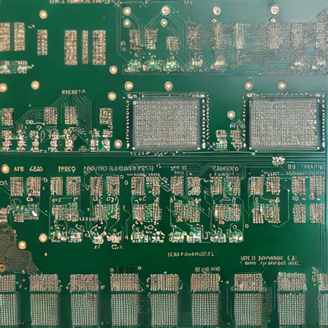
5. Graphic transfer
Purpose: Graphic transfer is to transfer the image on the production film to the board
Process: (blue oil process): grinding board → printing the first side → drying → printing the second side → drying → exposure → developing → inspection; (dry film process): hemp board → pressing film → standing → alignment → exposure → standing → developing → inspection
6.Graphic electroplating
Purpose: Graphic electroplating is to electroplate a copper layer of required thickness and a gold, nickel or tin layer of required thickness on the exposed copper skin of the circuit pattern or on the hole wall.
Process: board up → degreasing → water washing twice → micro etching → water washing → pickling → copper plating → water washing → pickling → tin plating → water washing → board down
7. Film stripping
Purpose: Use NaOH solution to remove the anti-electroplating covering film layer to expose the non-circuit copper layer.
Process: Water film: insert rack → alkali dip → rinse → scrub → machine pass; dry film: place board → machine pass
8.Etching
Purpose: Etching is to use chemical reaction method to corrode the copper layer of non-circuit parts.
9.Green oil
Purpose: Green oil is to transfer the pattern of green oil film to the board, which plays a role in protecting the circuit and preventing tin from being deposited on the circuit when welding parts
Process: grinding plate → printing photosensitive green oil → brazing plate → exposure → developing; grinding plate → printing the first side → baking plate → printing the second side → baking plate
10.Characters
Purpose: Characters are a kind of mark that is easy to identify
Process: After the green oil is finally brazed → cooling and standing → adjusting the screen → printing characters → post-brazing
11.Gold-plated fingers
Purpose: A layer of nickel\gold layer of the required thickness is plated on the plug fingers to make them more hard and wear-resistant
Process: board → degreasing → washing twice → micro-etching → washing twice → pickling → copper plating → washing → nickel plating → washing → gold plating
12.Tin-plated board (a parallel process)
Purpose: Spraying tin is to spray a layer of lead tin on the exposed copper surface not covered with solder resist oil to protect the copper surface from corrosion and oxidation, so as to ensure good welding performance.
Process: micro-etching → air drying → preheating → rosin coating → solder coating → hot air leveling → air cooling → washing and air drying
13.Molding
Purpose: Through die stamping or CNC gong machine gong to produce the shape required by the customer, the molding methods include organic gong, beer board, hand gong, and hand cutting
Description: The precision of the data gong machine board and the beer board is higher, followed by the hand gong, and the hand-cut board can only make some simple shapes.
14.Testing
Purpose: Through 100% electronic testing, detect defects that affect functionality such as open circuits and short circuits that are not easily found visually.
Process: upper mold → plate placement → test → qualified → FQC visual inspection → unqualified → repair → return to test → OK → REJ → scrap
15.Final inspection
Purpose: Through 100% visual inspection of board appearance defects, and repair minor defects to avoid the outflow of problematic and defective boards.
Specific work process: incoming materials → check information → visual inspection → qualified → FQA spot check → qualified → packaging → unqualified → processing → inspection OK