
Skip to content
Andwin Circuits
  • Home
  • ProductsExpand
    • HDI multilayer PCB
    • Rigid Flex PCB
    • Flex pcb
    • Special PCBExpand
      • High Frequency PCBExpand
        • Rogers RO4350B PCB
        • Rogers RO4003 pcb
        • Rogers RO3003 PCB
        • Rogers 5880 PCB
        • DICLAD 527 PCB
        • Taconic TLX series
        • Taconic TLX-8 RF PCB
        • Taconic TLX-9 RF PCB
      • High speed pcbExpand
        • Megtron 6 High Speed PCB
        • TU-872 SLK Sp High Speed
      • High TG PCBExpand
        • SHENGYI SH260 PCB
        • ISOLA 370HR PCB
        • ISOLA IS410 PCB
        • ISOLA IS420 PCB
      • Heavy copper PCB
      • Copper coin pcb
      • Copper inlay PCB
    • Metal Core PCBExpand
      • Copper core pcb
      • Aluminum PCB
      • 2 Layers Aluminum PCB
      • Direct thermal MCPCB
      • 2 Layers Direct Thermal
    • Ceramic PCBExpand
      • DPC ceramic PCB
      • DBC ceramic PCB
      • Thick film Ceramic PCB
      • Al2O3 Alumina PCB
      • AIN ALN ceramic PCB
      • IGBT Ceramic PCB
  • ServiceExpand
    • PCB Assembly
    • Quick turn PCB assembly
    • PCBA conformal coating
  • IndustryExpand
    • Telecommunication
    • IoT and Wireless
    • Industrial Control
    • Thermal management
    • Power and Energy
    • IC test board
    • Automative
    • Medical
  • CapabilityExpand
    • Rigid PCB
    • Rigid flex PCB
    • Metal core PCB
    • PCB Assembly
  • TechnologyExpand
    • Blogs
    • Via in pad
    • PCB E-test
    • PCB stack up
    • MCPCB panelization
    • Controlled impedance PCB
  • AboutExpand
    • About us
    • Certification
    • Factory Tour
  • Contact
Andwin Circuits
Home / Typical PCB Layout Problems and Their Impact

Typical PCB Layout Problems and Their Impact

ByGrace July 29, 2025July 29, 2025

Countless application examples of industrial, scientific, and medical radio frequency (ISM-RF) products demonstrate the vulnerability of printed circuit board (PCB) layout to various flaws. It’s common to observe significant differences in performance between the same IC mounted on two different boards. Variations in operating conditions, harmonic emissions, interference immunity, startup time, and other factors highlight the importance of PCB layout in a successful design.

This article lists various design oversights, explores how each can lead to circuit failure, and provides recommendations for avoiding these design flaws. This article uses a two-layer PCB with FR-4 dielectric and 0.0625-inch thickness, with the bottom layer grounded. The operating frequency ranges from 315 MHz to 915 MHz, with Tx and Rx power levels ranging from -120 dBm to +13 dBm. Table 1 lists some potential PCB layout issues, their causes, and their impact.
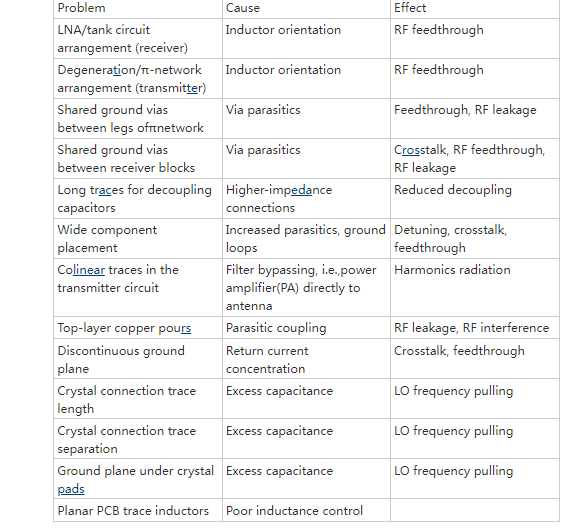
Most of these problems stem from a few common causes, which will be discussed individually.

Contact us for PCB quote now |

Inductor Orientation

When two inductors (or even two PCB traces) are placed close together, mutual inductance occurs. The magnetic field generated by the current in the first circuit excites the current in the second circuit (Figure 1). This process is similar to the interaction between the primary and secondary windings of a transformer. When the two currents interact through the magnetic field, the resulting voltage is determined by the mutual inductance LM:

Where YB is the error voltage injected into circuit B, and IA is the current acting in circuit A. LM is very sensitive to circuit spacing, the inductor loop area (i.e., magnetic flux), and the loop orientation. Therefore, the optimal balance between compact circuit layout and reduced coupling is to properly orient all inductors.
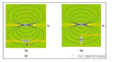
Figure 1. Magnetic field lines show that mutual inductance is related to inductor orientation.

Contact us for PCB quote now |

Circuit B is oriented so that its current loop is parallel to the magnetic field lines of Circuit A. To achieve this, the inductors are positioned as perpendicular to each other as possible. Refer to the layout of the low-power FSK superheterodyne receiver evaluation (EV) kit (MAX7042EVKIT) (Figure 2). The three inductors (L3, L1, and L2) on this board are very close together. Arranging them at 0°, 45°, and 90° angles helps reduce mutual inductance.
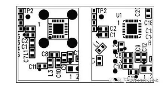
Figure 2. Two different PCB layouts are shown. One layout has an improper component orientation (L1 and L3), while the other has a more appropriate orientation.

In summary, the following principles should be followed:

Inductors should be spaced as far apart as possible.

Inductors should be arranged at right angles to minimize crosstalk between them.

Contact us for PCB quote now |

Post Tags: #aluminum clad pcb#aluminum core pcb#aluminum pcb#assemble pcb#pcb design#PCB layout

Post navigation

Previous Previous
Switch Mode Power Supply PCB Layout Techniques
NextContinue
The automotive electronics PCB market has broad potential.

Search

Search

Products

  • HDI Multilayer PCB
  • Rigid Flex PCB
  • Flex pcb
  • High Frequency PCB
  • High speed pcb
  • Heavy copper PCB
  • Metal Core PCB
  • Ceramic PCB

Address

Andwin Circuits Co.,Limited
Email: sales@andwinpcb.com
Tel: +86 755 2832 9394
Fax:+86 755 2992  6717
ADD:1-2F-1217,HouDeQun Industrial park,
NanTing RD NO.56,ShaJing,BaoAn,Shenzhen 518104,GuangDong,China

Products

  • HDI Multilayer PCB
  • Rigid Flex PCB
  • Flex pcb
  • High Frequency PCB
  • High speed pcb
  • Heavy copper PCB
  • Metal Core PCB
  • Ceramic PCB

Technology

  • Blogs
  • Via in pad
  • PCB E-test
  • PCB stack up
  • Metal core PCB panelization
  • Controlled impedance PCB

CERTIFICATION

Certification >>


Copyright© 2003 - 2026 Andwin | All Rights Reserved | Powered by Andwin

Scroll to top
  • Home
  • Products
    • HDI multilayer PCB
    • Rigid Flex PCB
    • Flex pcb
    • Special PCB
      • High Frequency PCB
        • Rogers RO4350B PCB
        • Rogers RO4003 pcb
        • Rogers RO3003 PCB
        • Rogers 5880 PCB
        • DICLAD 527 PCB
        • Taconic TLX series
        • Taconic TLX-8 RF PCB
        • Taconic TLX-9 RF PCB
      • High speed pcb
        • Megtron 6 High Speed PCB
        • TU-872 SLK Sp High Speed
      • High TG PCB
        • SHENGYI SH260 PCB
        • ISOLA 370HR PCB
        • ISOLA IS410 PCB
        • ISOLA IS420 PCB
      • Heavy copper PCB
      • Copper coin pcb
      • Copper inlay PCB
    • Metal Core PCB
      • Copper core pcb
      • Aluminum PCB
      • 2 Layers Aluminum PCB
      • Direct thermal MCPCB
      • 2 Layers Direct Thermal
    • Ceramic PCB
      • DPC ceramic PCB
      • DBC ceramic PCB
      • Thick film Ceramic PCB
      • Al2O3 Alumina PCB
      • AIN ALN ceramic PCB
      • IGBT Ceramic PCB
  • Service
    • PCB Assembly
    • Quick turn PCB assembly
    • PCBA conformal coating
  • Industry
    • Telecommunication
    • IoT and Wireless
    • Industrial Control
    • Thermal management
    • Power and Energy
    • IC test board
    • Automative
    • Medical
  • Capability
    • Rigid PCB
    • Rigid flex PCB
    • Metal core PCB
    • PCB Assembly
  • Technology
    • Blogs
    • Via in pad
    • PCB E-test
    • PCB stack up
    • MCPCB panelization
    • Controlled impedance PCB
  • About
    • About us
    • Certification
    • Factory Tour
  • Contact
Search