Understanding Flex PCB Dielectric Constant: Key Considerations for High-Performance Designs
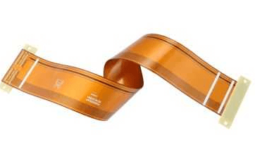
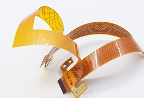
Flexible printed circuit boards (Flex PCBs) have revolutionized the electronics industry by enabling lightweight, compact, and versatile designs. They are widely used in applications such as wearable devices, medical equipment, aerospace systems, and consumer electronics. One of the critical parameters that influence the performance of Flex PCBs is the dielectric constant (Dk) of the substrate material. The dielectric constant plays a vital role in determining signal integrity, impedance matching, and overall electrical performance. This article explores the concept of dielectric constant in Flex PCBs, its impact on design, and best practices for selecting and optimizing materials.
What Is Dielectric Constant?
The dielectric constant (Dk), also known as relative permittivity, is a measure of a material’s ability to store electrical energy in an electric field. It is defined as the ratio of the permittivity of the material to the permittivity of free space (a vacuum). In simpler terms, the dielectric constant indicates how much a material can concentrate electric flux.
For PCB substrates, the dielectric constant affects several key electrical properties:
- Signal Propagation Speed: The speed at which electrical signals travel through the substrate is inversely proportional to the square root of the dielectric constant. Lower Dk values result in faster signal propagation.
- Impedance Matching: The dielectric constant influences the characteristic impedance of transmission lines, which is critical for minimizing signal reflections and ensuring efficient power transfer.
- Capacitance: The dielectric constant affects the capacitance between conductive traces, which can impact signal integrity and crosstalk.
- Loss Tangent: While not the same as dielectric constant, the loss tangent (Df) is often related. Materials with lower Dk values tend to have lower loss tangents, reducing signal attenuation.
Importance of Dielectric Constant in Flex PCBs
In Flex PCBs, the dielectric constant is particularly important due to the unique challenges posed by flexible materials and dynamic operating environments. Here are some reasons why Dk matters in Flex PCB design:
- Signal Integrity: Flex PCBs are often used in high-frequency applications, such as RF (radio frequency) and microwave circuits, where signal integrity is critical. A stable and predictable dielectric constant ensures consistent performance.
- Impedance Control: Maintaining precise impedance is essential for minimizing signal reflections and ensuring efficient power transfer. The dielectric constant directly affects the impedance of transmission lines.
- Miniaturization: Flex PCBs are commonly used in compact devices where space is at a premium. A lower dielectric constant allows for tighter trace spacing and smaller form factors without compromising performance.
- Flexibility and Durability: The dielectric constant of flexible materials must remain stable under bending, twisting, and other mechanical stresses to ensure reliable operation.
Factors Influencing Dielectric Constant in Flex PCBs
The dielectric constant of a Flex PCB substrate is influenced by several factors, including material composition, frequency, temperature, and humidity. Understanding these factors is essential for selecting the right material and optimizing design performance.
1. Material Composition
- The base material of the substrate (e.g., polyimide, polyester, or liquid crystal polymer) has a significant impact on the dielectric constant.
- Polyimide is the most common material for Flex PCBs due to its excellent thermal stability, flexibility, and moderate dielectric constant (typically around 3.4–3.5 at 1 MHz).
2. Frequency
- The dielectric constant of most materials varies with frequency. At higher frequencies, the dielectric constant tends to decrease, which can affect signal propagation and impedance.
- Designers must consider the operating frequency range when selecting materials and designing circuits.
3. Temperature
- Temperature changes can cause variations in the dielectric constant, particularly in materials with high thermal expansion coefficients.
- Flex PCBs used in high-temperature environments must use materials with stable dielectric properties over a wide temperature range.
4. Humidity
- Moisture absorption can alter the dielectric constant of some materials, leading to performance degradation.
- Polyimide, for example, has low moisture absorption, making it suitable for humid environments.
5. Additives and Fillers
- Some substrate materials include additives or fillers to enhance mechanical or thermal properties. These additives can affect the dielectric constant and must be carefully considered during material selection.

Common Flex PCB Materials and Their Dielectric Constants
The choice of substrate material is critical for achieving the desired dielectric constant and overall performance. Here are some commonly used Flex PCB materials and their typical dielectric constants:
- Polyimide (PI):
- Dielectric Constant: ~3.4–3.5 at 1 MHz
- Advantages: Excellent thermal stability, flexibility, and low moisture absorption.
- Applications: Aerospace, medical devices, consumer electronics.
- Liquid Crystal Polymer (LCP):
- Dielectric Constant: ~2.9–3.1 at 1 MHz
- Advantages: Low moisture absorption, stable dielectric properties over a wide frequency range.
- Applications: High-frequency RF circuits, 5G devices.
- Polyester (PET):
- Dielectric Constant: ~3.2–3.3 at 1 MHz
- Advantages: Low cost, good flexibility.
- Applications: Low-cost consumer electronics, disposable medical devices.
- Fluoropolymers (e.g., PTFE):
- Dielectric Constant: ~2.1–2.5 at 1 MHz
- Advantages: Extremely low dielectric constant and loss tangent, excellent high-frequency performance.
- Applications: RF and microwave circuits, satellite communications.
Design Considerations for Optimizing Dielectric Constant
To maximize the performance of Flex PCBs, designers must carefully consider the dielectric constant during the design process. Here are some best practices:
- Material Selection:
- Choose a substrate material with a dielectric constant that meets the requirements of your application.
- Consider the operating frequency, temperature range, and environmental conditions when selecting materials.
- Impedance Matching:
- Use impedance calculators or simulation tools to design transmission lines with the correct width and spacing for the chosen dielectric constant.
- Ensure consistent impedance across the entire circuit to minimize signal reflections.
- Layer Stackup:
- Optimize the layer stackup to achieve the desired electrical performance. For example, use low-Dk materials for signal layers and higher-Dk materials for power and ground planes.
- Minimize the number of layers to reduce complexity and cost.
- Signal Integrity:
- Use differential pairs and controlled impedance traces to maintain signal integrity in high-frequency applications.
- Avoid sharp bends and discontinuities in traces, which can cause impedance mismatches.
- Thermal Management:
- Consider the thermal properties of the substrate material, as temperature variations can affect the dielectric constant.
- Use thermal vias and heat sinks to dissipate heat and maintain stable performance.
- Testing and Validation:
- Perform electrical testing to validate the dielectric constant and impedance of the fabricated PCB.
- Use time-domain reflectometry (TDR) or network analyzers to measure signal integrity and impedance.
Applications and Case Studies
The dielectric constant of Flex PCBs plays a critical role in various applications. Here are some examples:
- Wearable Devices:
- Flex PCBs in smartwatches and fitness trackers require low-Dk materials to ensure fast signal propagation and minimal signal loss.
- Polyimide is commonly used due to its balance of flexibility and electrical performance.
- Medical Equipment:
- Medical devices such as endoscopes and implantable sensors require stable dielectric properties to ensure reliable operation.
- LCP is often used for its low moisture absorption and stable Dk over a wide frequency range.
- Aerospace Systems:
- Flex PCBs in aerospace applications must withstand extreme temperatures and vibrations while maintaining consistent electrical performance.
- Fluoropolymers like PTFE are used for their low dielectric constant and excellent high-frequency performance.
- 5G and RF Circuits:
- High-frequency applications such as 5G infrastructure and RF modules require materials with low dielectric constants and loss tangents.
- LCP and PTFE are preferred for their superior high-frequency properties.
Challenges and Solutions
Designing Flex PCBs with the right dielectric constant presents several challenges, but these can be addressed with the right strategies:
- Material Trade-offs:
- Challenge: Balancing dielectric constant with other material properties such as flexibility, thermal stability, and cost.
- Solution: Select materials that offer the best compromise for your specific application.
- Frequency Dependence:
- Challenge: Dielectric constant varies with frequency, affecting performance in wideband applications.
- Solution: Use materials with stable dielectric properties over the desired frequency range.
- Environmental Factors:
- Challenge: Temperature and humidity variations can alter the dielectric constant.
- Solution: Choose materials with low moisture absorption and stable thermal properties.
- Manufacturing Constraints:
- Challenge: Some low-Dk materials are more difficult to process and may require specialized equipment.
- Solution: Work with experienced manufacturers who have expertise in handling advanced materials.
Conclusion
The dielectric constant is a critical parameter in the design of Flex PCBs, influencing signal integrity, impedance matching, and overall electrical performance. By understanding the factors that affect dielectric constant and following best practices in material selection and design, engineers can create Flex PCBs that meet the demands of even the most challenging applications.
As the use of Flex PCBs continues to grow in industries such as wearable technology, medical devices, and aerospace, the importance of optimizing dielectric constant will only increase. By leveraging advanced materials, simulation tools, and testing techniques, designers can push the boundaries of what is possible with Flex PCBs, enabling innovative solutions for the electronics of tomorrow.