
What adverse conditions will occur during PCB welding? What are the main reasons?
PCB (Printed Circuit Board) welding is the process of connecting electronic components to PCB. In this process, various undesirable conditions may occur, which will adversely affect the welding quality and the performance of electronic equipment. PCB (Printed Circuit Board) welding is one of the key links in the electronic manufacturing process. However, various undesirable conditions may occur during the welding process, which may affect the welding quality and the performance of electronic products. This article will introduce some common PCB welding defects and their main causes.

Welding defects:
- Welding open circuit: Welding open circuit means that there is no good welding connection between the electronic component and the PCB, resulting in the inability of the current to pass smoothly. This may be caused by insufficient melting of the solder, too low welding temperature, insufficient welding time, etc.
- Welding short circuit: Welding short circuit refers to an unintentional welding connection between electronic components or between them and the PCB, resulting in abnormal current. Common reasons include solder overflow, wire crossing, etc.
- Inaccurate positioning: During welding, inaccurate positioning of electronic components can also lead to undesirable conditions. This may be due to positioning errors during assembly, insufficient equipment accuracy, etc.
- Cold welding/dry false welding: Cold welding means that the solder is not completely melted during welding, resulting in insufficient solder strength; dry false welding means that the solder is in poor contact with the welding point, resulting in the welding point becoming loose during use. This may be caused by insufficient welding temperature, poor solder quality, insufficient welding time, etc.
- Pad damage: The pad refers to the metal sheet on the PCB used for welding with electronic components. Pad damage may be caused by excessive welding force, excessive welding temperature, etc. Damaged pads will affect the stability and reliability of welding.
Main reasons:
- Incorrect process parameters: Poor welding is often caused by incorrect process parameter settings. The selection and control of parameters including welding temperature, welding time, welding pressure, etc. are the key to ensuring welding quality.
- Equipment problems: The quality and performance of welding equipment will also affect the welding quality. The accuracy, stability, heating uniformity, etc. of the equipment will affect the welding results.
- Material quality: The quality of welding materials is also an important reason for poor welding. The quality of solder wire, flux, etc. will affect the welding results.
- Improper operation: The technical level and experience of welding operation are also important factors affecting the quality of welding. Operators should follow the correct operating procedures and steps during the welding process to ensure the quality of welding.
- Design defects: Sometimes poor welding is also related to PCB design. Poor design may lead to problems such as too small solder joint spacing and unreasonable pad structure, which in turn affects the quality of welding.
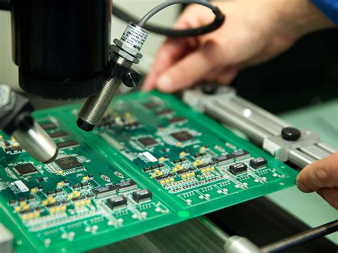
In the actual welding process, in order to reduce the occurrence of adverse conditions, the following measures can be taken:
- Optimize welding process parameters to ensure that parameters such as temperature, time, and pressure are appropriate.
- Quality control, select high-quality welding equipment and welding materials.
- Strengthen employee training to improve operators’ welding technology and quality awareness.
- Strengthen the weldability of PCB design to ensure the rationality of pad structure and solder joint spacing.
Poor or incomplete welding: Poor or incomplete welding means that the solder joint is not fully formed or the quality does not meet the standard during the welding process, which may be caused by the following reasons:
Improper welding temperature, time or welding pressure leads to poor quality of solder joints.
Improper use of flux results in unreduced soldering surface tension and incomplete soldering. Contaminants or oxides on the PCB surface prevent the solder from fully contacting the soldering surface. Tin ball or tin droplet formation: Tin ball or tin droplet refers to the formation of spherical or droplet-shaped solder during the soldering process, which may be caused by the following reasons: The soldering temperature is too high or the soldering time is too long, causing the solder to be excessively liquefied and flow, forming tin balls or tin droplets. Incorrect solder composition or low purity leads to poor solder fluidity, forming tin balls or tin droplets.
Uneven or inaccurate solder: Uneven or inaccurate solder refers to the uneven distribution of solder during the soldering process or failure to apply it to the solder joints that should be applied, which may be caused by the following reasons: Incorrect setting of soldering process parameters, such as soldering temperature, time or soldering pressure. Instability of soldering equipment or tools, resulting in uneven or inaccurate solder distribution. Insufficient technical level and experience of operators, unable to accurately apply solder.
In short, poor soldering can have an adverse effect on the performance and reliability of electronic equipment. By optimizing the welding process, improving equipment accuracy and stability, strengthening employee training and optimizing PCB design, the occurrence of poor welding can be effectively reduced and the welding quality and reliability can be improved.