
Why is using PCB vias crucial for reducing EMI?
Many children love donuts. During those relaxing moments with their children, these adorable little ones inevitably become curious and ask a thousand questions. They’ll often ask how donuts are made and why they have a hole in the center. As parents, we’ll try our best to satisfy their curiosity, but often our efforts fall short. We’re not all-knowing encyclopedias, and we don’t know why donuts have holes. Fortunately, we can easily open our mobile browsers and search online for answers.
Unless you have a curious child who’ll search Baidu to answer their “why,” you might not care about why donuts have a hole. Similarly, as an electronics professional, you’ll want to understand why mounting holes are placed in PCBs and might search Google for information on these types of holes. PCB mounting holes are a crucial element in electronics design. Every PCB designer should understand their purpose and basic design. Furthermore, when mounting holes are connected to ground, unnecessary post-installation trouble can be avoided.
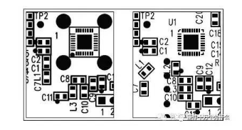
How to Use PCB Vias to Reduce EMI?
As the name suggests, PCB mounting holes help secure the PCB to the enclosure. While this is only their physical and mechanical purpose, PCB mounting holes also have an electromagnetic function to reduce electromagnetic interference (EMI). EMI-sensitive PCBs are often placed in metal enclosures. To effectively reduce EMI, plated PCB mounting holes need to be connected to ground. This ground shielding function directs any electromagnetic interference from the metal enclosure to the ground.
A common question new designers ask is which ground they should be connected to. In common electronic devices, there are signal ground, chassis ground, and ground. As a rule of thumb, do not connect mounting holes to the signal ground. The signal ground serves as the reference ground for the electronic components in your circuit design, and introducing electromagnetic interference there is undesirable.
You should connect to the chassis ground. This is the point where all ground connections for the enclosure converge. The chassis ground should be connected at a single point, preferably using a star connection. This avoids ground loops and multiple ground connections. Multiple ground connections can cause slight voltage differences and current to flow between chassis grounds. The chassis ground should then be connected to earth for safety reasons.
Why is proper ground connection so important?
If the PCB’s housing is a metal enclosure, the entire metal enclosure serves as the ground. The 220V power supply ground wire should be connected to earth, as should all connectors and screws. This ensures that incoming interference during EMC testing is directly discharged from the metal enclosure to earth, ensuring it does not interfere with internal systems. Furthermore, EMC protection devices must be present at each connector and placed close to the connector.
If the enclosure is plastic, it’s best to have a metal plate embedded within it. If this isn’t possible, consider the wiring layout carefully. Sensitive signal lines (clock, reset, crystal, etc.) should be grounded, and filtering networks (for chips, crystal, and power supplies) should be added.
Connecting plated mounting holes to the chassis ground is a best practice, but it’s not the only best practice. To ensure your equipment is protected, your chassis ground must be connected to a proper ground terminal. For example, if you build an automated parking payment machine without proper grounding, you might have customers complain of “electric shocks” while paying. This can happen when a customer touches an uninsulated metal part of the casing.
You can also receive a minor electric shock when the chassis of a computer power supply isn’t properly grounded. This can also happen when the ground cable connecting the power outlet to the building’s ground is disconnected. This can result in a floating ground on the corresponding machine.
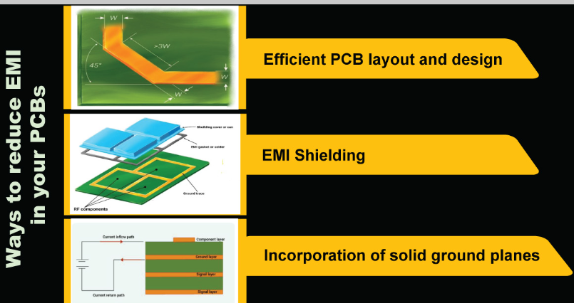
EMI shielding relies on a proper ground connection. Having a floating ground connection not only exposes your customers to minor electric shocks, but can also endanger user safety if your equipment shorts out. As shown in the figure below, proper grounding is important for both safety and EMI shielding.
Basic Tips for Designing PCB Mounting Holes
PCB mounting holes are frequently used in design. When designing mounting holes, there are a few simple, basic guidelines. First, pay attention to the mounting hole coordinates. Errors here will directly result in your PCB not being properly mounted in its enclosure. Also, ensure that the mounting hole size is appropriate for the screws you choose.
As a general rule, avoid placing mounting holes too far from the edge of the PCB. Too little dielectric material at the edge can cause cracks in the PCB during installation or removal. You should also allow ample clearance between the mounting holes and other components.