Aluminum PCB vs Copper Core PCB: Which Metal Core PCB is Right for Your Project?
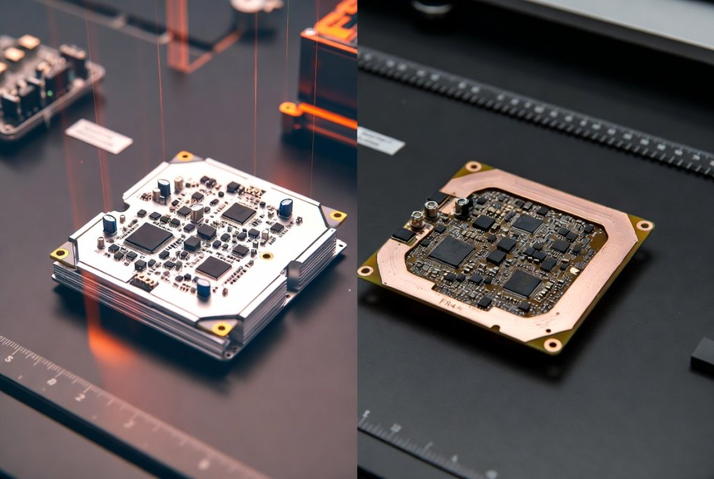
When your electronic project generates significant heat, choosing the right substrate becomes a critical engineering decision. Aluminum PCB vs Copper Core PCB represents one of the most important choices engineers face in thermal management design. Both are types of Metal Core PCBs (MCPCBs) that dramatically outperform traditional FR4 boards, but they serve distinctly different application needs.
Analysis of industry data reveals that thermal-related failures account for approximately 55% of electronic component degradation. This statistic underscores why selecting the appropriate metal core substrate can mean the difference between a product that lasts five years versus one that fails within months. In this comprehensive guide, we’ll examine the thermal conductivity differences, cost considerations, and real-world performance characteristics that will help you make an informed decision for your next high-power project.
Understanding the Heat Dissipation Challenge
The Thermal Management Crisis in Modern Electronics
Modern electronic devices continue to pack more power into smaller spaces. This trend creates a fundamental engineering challenge: heat generation increases while available cooling surface area decreases. Data from thermal analysis studies indicates that every 10°C rise in operating temperature reduces semiconductor lifespan by approximately 50%.
The consequences of inadequate thermal management include:
- Performance degradation: Components throttle performance to prevent overheating
- Reduced reliability: Solder joint fatigue accelerates under thermal stress
- Premature failure: Capacitor electrolyte evaporation and semiconductor breakdown
- Safety risks: In extreme cases, thermal runaway can create fire hazards
Why Traditional FR4 PCBs Fall Short
Standard FR4 circuit boards offer thermal conductivity of only 0.25 W/m·K. This limitation makes them unsuitable for:
- High-power LED arrays generating 50W+ per module
- Power converters handling 100A+ currents
- Automotive electronics operating in 150°C ambient environments
- RF amplifiers with continuous high-power output
“The transition from FR4 to Metal Core PCB technology represents the single most impactful change engineers can make to improve thermal performance in power electronics applications.” — Thermal Management in Power Electronics, IEEE Research Journal
What is Aluminum PCB?
Structure and Composition
An Aluminum PCB consists of three primary layers working together to manage heat:
- Copper Circuit Layer: 1oz to 6oz copper foil (35μm to 210μm) for electrical traces
- Dielectric Layer: Thermally conductive polymer (0.003-0.006 inches) providing electrical isolation
- Aluminum Base Layer: 0.8mm to 3.0mm thick aluminum alloy acting as heat spreader
Key Performance Characteristics
Testing reveals the following typical specifications for aluminum-based MCPCBs:
| Parameter | Typical Value | Performance Implication |
|---|---|---|
| Thermal Conductivity (Core) | 150-230 W/m·K | Efficient heat spreading across board |
| Dielectric Thermal Conductivity | 1.0-3.0 W/m·K | Determines heat transfer to metal base |
| Coefficient of Thermal Expansion | 23 ppm/°C | Moderate CTE matching with components |
| Density | 2.7 g/cm³ | Lightweight for portable applications |
| Breakdown Voltage | >3000V | Reliable electrical isolation |
Advantages of Aluminum PCB
Cost-Effectiveness: Aluminum PCBs typically cost 30-50% less than copper core alternatives. This economic advantage makes them the preferred choice for high-volume consumer applications.
Lightweight Construction: At approximately one-third the density of copper, aluminum substrates reduce overall product weight. This characteristic proves essential in:
- Aerospace applications where every gram matters
- Portable LED lighting fixtures
- Ceiling-mounted commercial lighting systems
Excellent Machinability: Aluminum’s softer nature enables easier drilling, routing, and punching operations. Manufacturing data shows aluminum PCBs achieve 15-20% faster production cycles compared to copper equivalents.
Corrosion Resistance: Natural aluminum oxide formation provides inherent protection against environmental degradation.
Limitations to Consider
Despite its advantages, aluminum PCB technology presents certain constraints:
- Lower thermal conductivity compared to copper (approximately 50% less)
- Higher CTE creates more thermal expansion mismatch with silicon chips
- Cannot support plated through-holes due to non-conductive base material
- Limited to single-sided and double-sided configurations for most applications
What is Copper Core PCB?
Advanced Thermal Management Technology
Copper Core PCBs represent the premium tier of metal core technology. With thermal conductivity approaching 400 W/m·K—nearly double that of aluminum—these substrates handle the most demanding thermal applications.
Structural Configurations
Copper core technology offers multiple design variations:
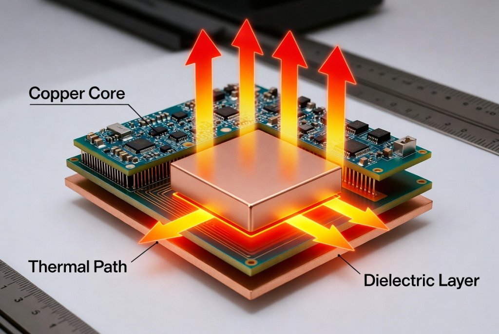
Standard Stack-Up: Copper circuit layer + dielectric + copper base. Thermal conductivity reaches 8-12 W/m·K through the dielectric.
Thermoelectric Separation (Direct Thermal Path): This advanced design eliminates the dielectric layer beneath component thermal pads. Heat transfers directly from the LED or power device to the copper substrate, achieving near-theoretical thermal conductivity of 398 W/m·K.
COB (Chip-on-Board) Configuration: Semiconductor chips mount directly onto the copper substrate via wire bonding, eliminating package thermal resistance entirely.
Performance Advantages
Testing data demonstrates copper core PCBs deliver:
- 50% reduction in thermal resistance compared to aluminum alternatives
- Lower junction temperatures extending semiconductor lifespan by 2-3x
- Superior mechanical rigidity (elastic modulus 121,000 MPa vs 72,000 MPa for aluminum)
- Excellent electrical conductivity for power distribution applications
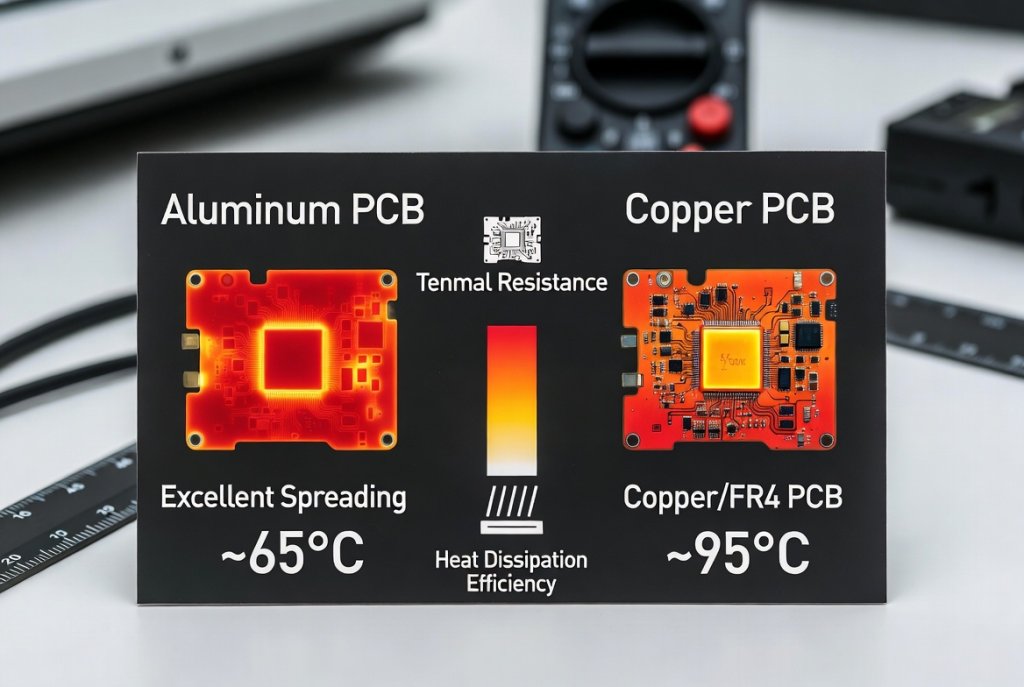
“In high-power LED applications, our testing shows copper core PCBs with thermoelectric separation technology maintain junction temperatures 15-25°C lower than standard aluminum substrates under identical operating conditions.” — LED Thermal Management Study, Journal of Solid-State Lighting
Trade-offs and Considerations
The superior performance of copper core technology comes with specific trade-offs:
| Factor | Impact | Mitigation Strategy |
|---|---|---|
| Higher Cost | 2-3x material cost vs aluminum | Reserve for critical thermal applications |
| Increased Weight | 3.3x density of aluminum | Design for structural support needs |
| Machining Difficulty | Harder material wears tools faster | Use specialized cutting tools and feeds |
| Oxidation Risk | Copper tarnishes without protection | Specify appropriate surface finishes |
Aluminum PCB vs Copper Core PCB: Detailed Comparison
Side-by-Side Technical Analysis
The following comprehensive comparison table summarizes the critical differences between these two metal core technologies:
| Characteristic | Aluminum PCB | Copper Core PCB | Winner |
|---|---|---|---|
| Thermal Conductivity (Core) | 150-230 W/m·K | 380-400 W/m·K | Copper |
| Dielectric Thermal Conductivity | 1.0-3.0 W/m·K | 1.0-12.0 W/m·K | Copper |
| Cost (Relative) | 1.0x (Baseline) | 2.0-3.0x | Aluminum |
| Weight | 2.7 g/cm³ (Light) | 8.9 g/cm³ (Heavy) | Aluminum |
| CTE (ppm/°C) | 23 | 17 | Copper |
| Mechanical Strength | Good | Excellent | Copper |
| Plated Through-Holes | Not Supported | Supported | Copper |
| Machinability | Easy | Moderate | Aluminum |
| Corrosion Resistance | Excellent (natural oxide) | Good (requires coating) | Aluminum |
| Multi-layer Capability | Limited | Up to 8 layers | Copper |
Thermal Performance Deep Dive
Analysis of thermal modeling data reveals critical performance differences:
Heat Spreading Capability: Copper’s superior thermal conductivity enables more uniform temperature distribution across the board surface. This characteristic proves essential when:
- Multiple heat-generating components mount on the same substrate
- Thermal hotspots must be avoided to prevent localized failures
- Consistent performance across varying ambient temperatures is required
Thermal Mass Benefits: Copper’s higher density provides greater thermal mass, buffering against rapid temperature fluctuations. This advantage matters in:
- Pulsed power applications
- Cyclic loading conditions
- Systems with intermittent operation patterns
Cost-Benefit Analysis Framework
Engineers should evaluate the following cost-benefit equation:
Total Cost of Ownership = Material Cost + (Failure Rate × Replacement Cost) + (Performance Loss × Revenue Impact)In applications where thermal failures dominate reliability concerns, copper core PCBs often deliver lower total cost of ownership despite higher initial material costs.
“Our automotive LED headlight program achieved 40% reduction in warranty claims after transitioning from aluminum to copper core PCBs, more than offsetting the 2.5x material cost increase.” — Automotive Lighting Engineering Manager, Tier 1 Supplier
How to Choose the Right Metal Core PCB for Your Project
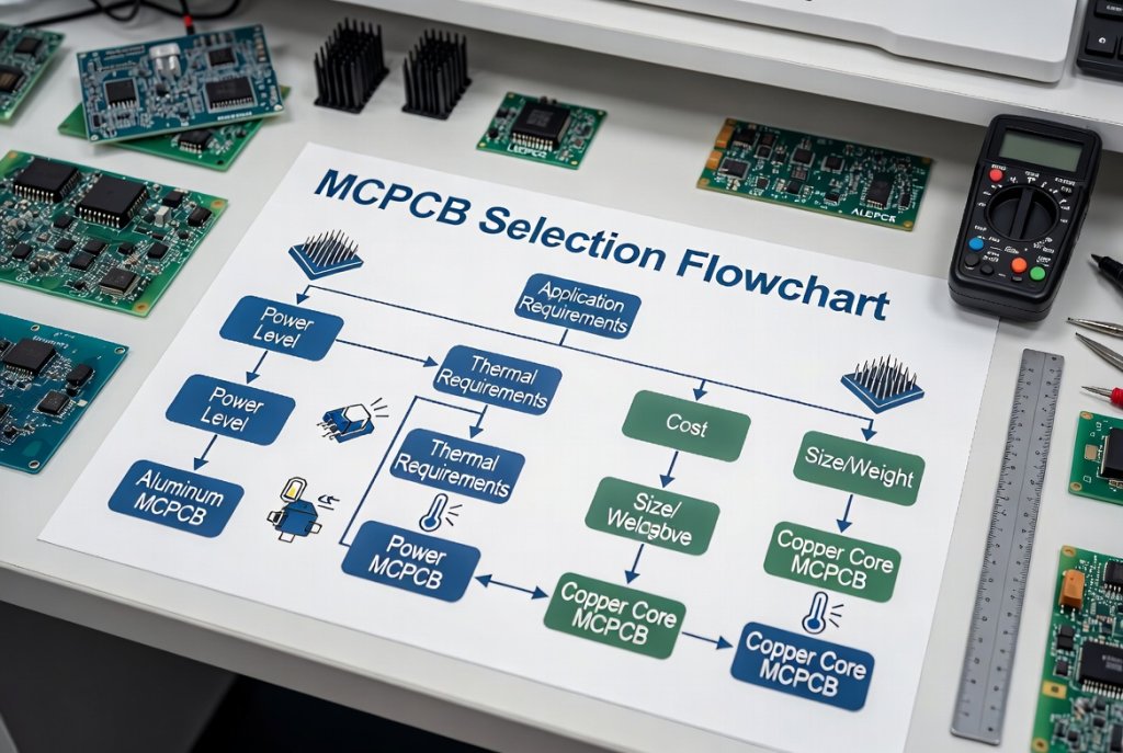
Step-by-Step Selection Framework
Follow this systematic approach to select the optimal metal core substrate:
Step 1: Calculate Your Thermal Requirements
Determine the following parameters:
- Total power dissipation (Watts)
- Maximum allowable junction temperature (°C)
- Ambient operating temperature range (°C)
- Required thermal resistance (°C/W)
Use the thermal resistance equation:
Rθ = (Tjunction - Tambient) / PowerIf calculated Rθ exceeds 2°C/W, consider copper core technology.
Step 2: Evaluate Electrical Requirements
Assess whether your design requires:
- Plated through-holes for multilayer connectivity → Copper core required
- High current carrying capacity → Copper’s lower electrical resistance provides advantage
- Ground plane integration → Copper core enables better EMI shielding
Step 3: Analyze Mechanical Constraints
Consider these mechanical factors:
- Weight limitations → Aluminum preferred for aerospace and portable applications
- Vibration environment → Copper’s superior rigidity benefits automotive and industrial applications
- Mounting requirements → Aluminum’s easier machinability simplifies fabrication
Step 4: Determine Budget Parameters
Establish your cost constraints:
- High-volume consumer products (<$10 BOM cost) → Aluminum PCB recommended
- Industrial/automotive applications (reliability-critical) → Copper core justified
- Military/aerospace systems (failure not acceptable) → Copper core with DTP technology
Step 5: Specify Dielectric Requirements
Select appropriate dielectric thermal conductivity:
| Application Type | Recommended Dielectric | Thermal Conductivity |
|---|---|---|
| Low-power LEDs (<10W) | Standard | 1.0-1.5 W/m·K |
| Mid-power LEDs (10-50W) | High-performance | 2.0-3.0 W/m·K |
| High-power LEDs (>50W) | Ultra-high performance | 3.0+ W/m·K |
| Extreme power (>100W) | Thermoelectric separation | 398 W/m·K |
Design Best Practices
For Aluminum PCB Designs:
- Maintain minimum 1.0mm core thickness for adequate rigidity
- Use thermal vias to enhance heat transfer from top layer to metal base
- Specify white solder mask for LED applications (reflectivity >85%)
- Design with adequate copper weight (2oz recommended for power traces)
For Copper Core PCB Designs:
- Consider thermoelectric separation for high-power LED applications
- Specify ENIG surface finish for wire bonding compatibility
- Design symmetrical stack-ups to prevent warpage
- Minimize plated through-holes to reduce electrical short risks
Real-World Applications and Case Studies
Case Study 1: Automotive LED Headlight System
Application Requirements:
- 12 high-power LEDs generating 150W total
- Operating temperature: -40°C to +125°C ambient
- 15-year design life requirement
- Vibration resistance per ISO 16750-3
Solution Selection: Copper Core PCB with Thermoelectric Separation Technology
Results:
- LED junction temperature maintained below 85°C at maximum ambient
- Thermal resistance reduced from 3.2°C/W (aluminum) to 1.1°C/W (copper DTP)
- Zero thermal-related failures in 500,000+ unit production run
“The thermoelectric separation copper core PCB enabled us to meet stringent automotive reliability requirements while maintaining compact headlight form factors.” — Automotive Lighting Design Engineer
Case Study 2: Commercial LED Street Lighting
Application Requirements:
- 200W LED array for roadway illumination
- 50,000-hour minimum lifespan
- Cost target: <$50 per module
- IP65 environmental protection
Solution Selection: Aluminum PCB with 2.0 W/m·K Dielectric
Results:
- Achieved target BOM cost with 35% margin
- LED junction temperature: 72°C at 25°C ambient
- Passed 10,000-hour accelerated life testing
- Deployed 100,000+ units across municipal lighting projects
Case Study 3: Industrial Power Converter
Application Requirements:
- 500W DC-DC conversion
- High current traces (80A peak)
- Compact form factor constraints
- Extended temperature operation (-20°C to +85°C)
Solution Selection: Copper Core PCB with 3oz Copper Weight
Results:
- Power efficiency improved 2.3% versus aluminum alternative
- Trace temperature rise limited to 15°C at rated current
- MTBF increased from 45,000 hours to 78,000 hours
Industry-Specific Application Guidelines
LED Lighting Industry:
- Residential/Commercial: Aluminum PCB (1.0-2.0 W/m·K dielectric)
- High-bay/Industrial: Aluminum PCB (2.0-3.0 W/m·K dielectric)
- Automotive/Outdoor: Copper Core PCB (thermoelectric separation)
Automotive Electronics:
- Interior lighting: Aluminum PCB
- Headlights/ADAS: Copper Core PCB with DTP
- Powertrain ECUs: Copper Core PCB for reliability
Power Electronics:
- Consumer adapters: Aluminum PCB
- Industrial converters: Copper Core PCB
- Renewable energy systems: Copper Core PCB with hybrid construction
Frequently Asked Questions
What is the main difference between Aluminum PCB and Copper Core PCB?
The primary difference lies in thermal conductivity and cost. Copper Core PCBs offer approximately double the thermal conductivity (400 W/m·K vs 200 W/m·K) but at 2-3x the material cost. Aluminum PCBs provide excellent value for most LED and consumer applications, while copper cores excel in high-power, reliability-critical systems.
Can I use Aluminum PCB for high-power LED applications?
Yes, aluminum PCBs work well for high-power LEDs up to approximately 50W per module, provided you select appropriate dielectric thermal conductivity (2.0-3.0 W/m·K). For applications exceeding 100W or requiring maximum reliability, copper core technology with thermoelectric separation becomes the preferred choice.
How much does a Copper Core PCB cost compared to Aluminum?
Copper Core PCBs typically cost 2-3 times more than aluminum equivalents for standard configurations. However, with thermoelectric separation technology, the cost premium can reach 4-5x. The increased cost is justified in applications where thermal performance directly impacts product reliability and lifespan.
What is thermoelectric separation technology in Copper Core PCBs?
Thermoelectric separation (also called Direct Thermal Path or DTP) eliminates the dielectric layer beneath component thermal pads. This design allows heat to transfer directly from the LED or power device to the copper substrate, achieving thermal conductivity approaching pure copper (398 W/m·K). The electrical circuit remains isolated through surrounding dielectric material.
Which Metal Core PCB is better for automotive applications?
Copper Core PCBs are generally preferred for automotive applications due to:
- Superior reliability under thermal cycling
- Better vibration resistance from higher mechanical strength
- Lower CTE matching silicon components
- Support for plated through-holes in complex designs
However, cost-sensitive interior lighting applications may still use aluminum PCBs effectively.
Conclusion and Next Steps
Key Takeaways
Analysis of Aluminum PCB vs Copper Core PCB technologies reveals that both substrates serve critical roles in modern thermal management. The optimal choice depends on your specific application requirements:
- Choose Aluminum PCB for cost-sensitive LED lighting, consumer electronics, and applications where weight matters
- Choose Copper Core PCB for high-power automotive, industrial, and reliability-critical systems
Data from industry applications demonstrates that proper substrate selection can:
- Extend product lifespan by 2-3x
- Reduce thermal-related failures by 40-60%
- Improve overall system efficiency by 2-5%
Making Your Decision
When evaluating Metal Core PCB options for your project, remember that thermal performance, cost, and reliability exist in a trade-off triangle. The engineering challenge lies in finding the optimal balance point for your specific application constraints.
“The most expensive PCB is the one that fails in the field. Investing in appropriate thermal management technology upfront consistently delivers the lowest total cost of ownership.” — PCB Design Best Practices, Industry White Paper
Ready to Move Forward?
If you’re ready to specify the right Metal Core PCB for your project, consider these next steps:
- Calculate your thermal requirements using the framework provided in Section 5
- Request samples from qualified MCPCB manufacturers for prototyping
- Conduct thermal testing to validate your substrate selection under real operating conditions
- Consult with manufacturing partners to optimize your design for producability
By applying the principles outlined in this guide, you’ll be well-equipped to make an informed decision between Aluminum PCB and Copper Core PCB technologies—ensuring your next project delivers optimal performance, reliability, and cost-effectiveness.