
Flex PCB in Medical Devices: Applications in Implantable Sensors and Endoscopes (2026)
Flexible PCBs have transformed medical device design by enabling miniaturization, biocompatibility, and mechanical durability where rigid boards can’t perform. From cochlear implants to disposable endoscopes, flex circuits provide the electrical reliability and physical flexibility that modern medical devices demand. Here’s what actually matters when designing flex PCBs for implantable sensors and endoscopic systems. For a broader understanding of why flexible circuits have become essential across all electronic sectors, see Why Are Modern Electronics Increasingly Using Flex PCB? A 2025 Engineering Analysis.
Why Flex PCBs Are Essential for Medical Devices
Implantable sensors need circuits that conform to curved anatomy, withstand body movement, and maintain performance in corrosive physiological environments. Endoscopes demand ultra-thin assemblies that fit through narrow channels while supporting high-resolution imaging sensors and LED illumination.
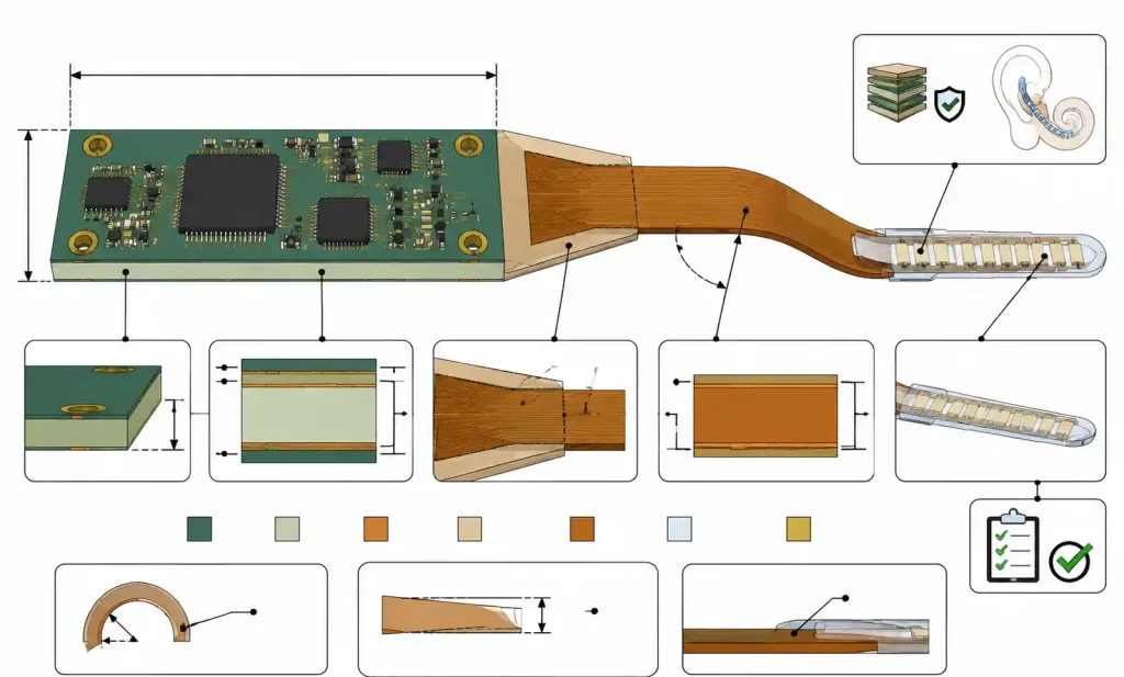
Flex PCBs deliver key advantages: they eliminate connectors and cables (critical for 2-5mm endoscope channels), survive repeated bending cycles (up to 100,000 flexes for articulation mechanisms), and use polyimide substrates that are biocompatible when properly encapsulated. Sterilization methods include gamma radiation, EtO, and autoclave cycles up to 134°C. The rigid-flex hybrid approach is particularly valuable in cochlear implants—signal processing mounts on a rigid section behind the ear, while a flexible tail routes electrode arrays into the cochlea.
If you’re comparing flex PCB technology against traditional rigid alternatives, see 5 Core Differences Between Flex PCB and Rigid PCB: A 2025 Engineering Guide.
Critical Design Parameters for Medical Flex PCBs
Medical flex PCBs need tighter tolerances than consumer electronics. Baseline minimum trace width is 3 mils with 3-mil spacing, though implantables often use 4/4 mil for better reliability. High-density designs like retinal implants can go to 2/2 mil, but that increases cost 30-50% and requires careful DFM review.
Bend radius is the most critical mechanical parameter. For static flex (bent once during assembly), use 6× total thickness minimum. For dynamic flex (repeated bending), use 10× thickness minimum, and consider 20× for applications exceeding 10,000 cycles. An endoscope articulation section with 0.2mm total thickness needs at least 4mm dynamic bend radius. For a detailed discussion of bend radius calculations in dynamic applications, see Flexible PCB Design Challenges in Smart Wearable Devices: Engineering Guide for Smartwatches and VR Headsets.
Copper weight affects flexibility and current capacity. Standard flex uses 1/2 oz for maximum flexibility. Implantables with microamp currents can use 1/3 oz to reduce stress and extend flex life. Power traces in endoscope illumination may need 1 oz on rigid sections, tapered to 1/2 oz in flex regions.
| Design Parameter | Static Flex | Dynamic Flex (<10K cycles) | Dynamic Flex (>10K cycles) | Implantable Device |
|---|---|---|---|---|
| Min trace/space | 3/3 mil | 4/4 mil | 5/5 mil | 4/4 mil |
| Copper weight | 1/2 oz | 1/2 oz | 1/3 oz | 1/3 to 1/2 oz |
| Min bend radius | 6× thickness | 10× thickness | 20× thickness | 10× thickness |
| Via annular ring | 3 mil | 4 mil | 5 mil | 4 mil |
| Coverlay opening | ±3 mil | ±2 mil | ±2 mil | ±2 mil |
| Layer count | 1-4 layers | 1-2 layers | 1-2 layers | 1-3 layers |
For implantable devices, prioritize reliability over density—one field failure in an implanted device can trigger millions in recalls. Dynamic flex regions should avoid vias entirely. When vias are unavoidable, stagger them at least 1mm away from the maximum stress area.
Material Selection: Biocompatibility and Performance
Substrate material must address biocompatibility, sterilization resistance, and long-term reliability in physiological conditions. Polyimide is the dominant choice, with specific formulations for medical use. To understand the material trade-offs between polyimide and other substrate options in flexible circuits, see PI vs PET for FPC: The Ultimate 2025 Engineering Guide for Material Selection.
Medical-grade polyimides (DuPont Pyralux AP, Rogers COOLSPAN) undergo controlled manufacturing that reduces ionic contamination and improves lot-to-lot consistency—critical for FDA submissions where material traceability is required.
For implantable devices with 10+ year service life, LCP (liquid crystal polymer) offers 0.04% moisture absorption—35× better than polyimide—and superior dimensional stability. But LCP costs 3-5× more and requires specialized processing.
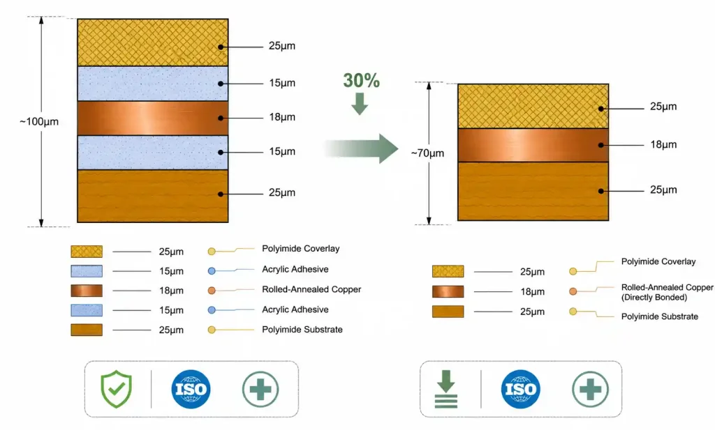
Adhesiveless polyimide eliminates the acrylic or epoxy adhesive layer found in standard flex laminates. This reduces total thickness by 25-40%, improves flexibility, and removes a potential source of leachable compounds that could fail biocompatibility testing. For Class III implantables, adhesiveless is strongly recommended despite 20-30% higher cost.
| Material Property | Standard Polyimide | Medical-Grade Polyimide | LCP Flex |
|---|---|---|---|
| Moisture absorption | 1.8-2.8% | 1.3-2.0% | 0.04% |
| Dielectric constant (1MHz) | 3.4-3.5 | 3.3-3.4 | 2.9-3.0 |
| Tg | 250-280°C | 260-300°C | 280-320°C |
| Sterilization methods | Gamma, EtO | Gamma, EtO, Autoclave | Gamma, EtO, Autoclave |
| Biocompatibility | USP Class VI (testing req’d) | USP Class VI, ISO 10993 | ISO 10993 certified |
| Cost multiplier | 1.0× | 1.3-1.5× | 3.0-5.0× |
For single-use endoscopes with gamma sterilization, standard polyimide offers the best cost-performance. For implantable sensors with 5-15 year service life, invest in medical-grade adhesiveless polyimide or LCP.
Coverlay material must withstand the sterilization method. Standard acrylic coverlays handle gamma and EtO but may delaminate during repeated autoclave cycles above 121°C. For reusable endoscopes requiring 200+ autoclave cycles, use polyimide coverlays with high-temperature adhesives rated for 150°C+ continuous exposure.
Layer Stackup Strategies
Implantable sensors typically use 1-2 layer constructions to minimize thickness. Neural probes, glucose sensors, and pressure monitors often use single-layer designs with traces on one side and a pseudo-ground plane created by selective etching or conductive ink on the opposite coverlay. This provides EMI shielding without adding a copper layer, keeping total thickness below 0.15mm.
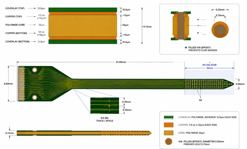
For a cortical neural probe with 64 channels, a 2-layer design uses 25μm polyimide core with 1/3 oz copper on both sides, yielding 0.11mm total thickness. Route high-speed signals on top with a continuous ground plane on bottom. Keep via diameter to 0.2mm and use filled vias to prevent fluid ingress.
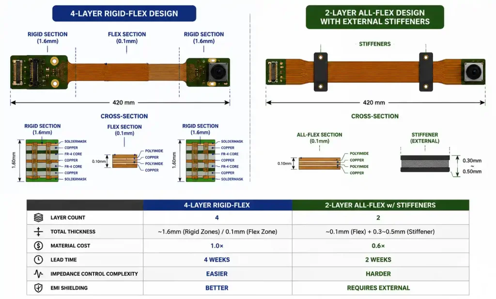
Endoscopic imaging systems need more complex stackups. A typical HD endoscope uses 4-layer rigid-flex: rigid sections at the connector and camera module, connected by a 2-layer flexible tail. The rigid sections use standard FR4 (1.6mm) for mechanical stability. The flexible interconnect uses 50μm polyimide core, routing differential MIPI CSI-2 signals on top and power/ground on bottom. To determine whether single-sided, double-sided, or multi-layer flex best suits your specific application, see Single-Sided vs. Double-Sided vs. Multi-Layer Flex PCBs: Which Fits Your Project?.
Impedance control is trickier in flex than rigid boards due to thinner dielectrics and tighter tolerances. A 2-layer flex with 50μm core (Dk 3.4) needs approximately 4-mil trace width with 4-mil spacing for 100-ohm differential impedance. Verify with your fabricator’s impedance calculator—adhesive layers and copper roughness affect final impedance.
DFM Considerations and Common Pitfalls
Vias in dynamic flex regions are the most common DFM mistake. Vias create stress concentration points where copper barrel cracks propagate during bending. Route traces continuously through flex zones without vias. If vias are unavoidable, position them at least 5mm from the active bend region.
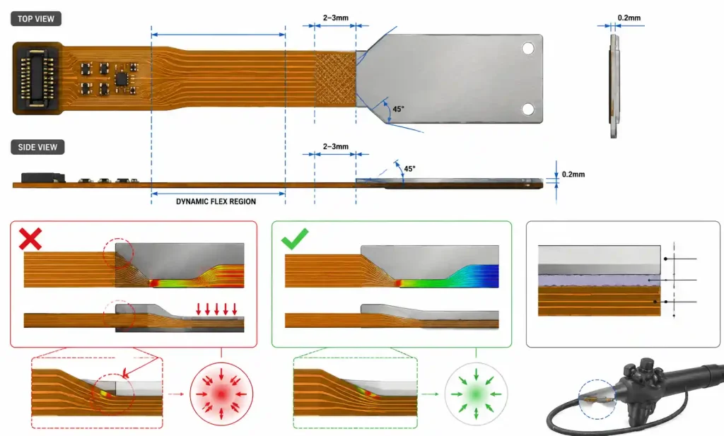
Stiffener placement requires careful planning. Taper stiffener edges at 45° angles rather than square corners, and maintain 2-3mm gap between stiffener edge and the dynamic flex zone. For endoscopes, use thin stainless steel stiffeners (0.1-0.2mm) under ZIF connectors instead of FR4 to minimize thickness.
Copper-to-edge clearance must be at least 0.3mm (12 mils) from any copper feature to the final cut edge. Flex circuits are routed using steel rule dies or laser cutting, both with ±0.1mm positional tolerance. Insufficient clearance exposes copper at the edge, creating corrosion sites that fail biocompatibility testing.
Coverlay registration is ±0.075mm in standard flex manufacturing—tighter than rigid PCB solder mask. Allow 3-4 mil clearance beyond the pad edge. For implantables, consider full coverlay coverage with selective laser ablation for pad exposure, which provides tighter registration (±0.05mm) and eliminates adhesive squeeze-out.
Reliability Testing and Regulatory Requirements
Medical flex PCBs need rigorous testing beyond commercial qualification.
Accelerated aging for implantable sensors: immersion in 0.9% saline at 37°C for 90+ days, followed by electrical testing. Passing criteria: <5% resistance change and >100MΩ insulation resistance.
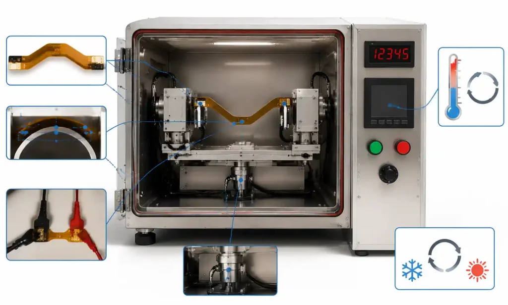
Dynamic flex testing for endoscope articulation: minimum 50,000 flex cycles at worst-case bend radius and temperature extremes (-20°C to +60°C storage, 20°C to 40°C operating). Monitor all traces for opens or resistance changes exceeding 10%.
Biocompatibility follows ISO 10993. Implantables require cytotoxicity, sensitization, irritation, systemic toxicity, genotoxicity, and implantation testing. Surface contact devices like endoscopes require a subset. Material records must trace all flex PCB materials back to master files with ISO 10993 data.
Sterilization validation must show the chosen method doesn’t degrade flex PCB performance. Gamma (25-50 kGy) causes polyimide discoloration but doesn’t affect electrical properties. EtO requires 24-48 hours aeration. Autoclave (121-134°C) is the most challenging—validate that coverlay adhesive maintains bond strength after 200+ cycles for reusable devices.
IPC-6013 Class 3 is recommended for all medical flex PCBs. Class 3 requires tighter copper thickness uniformity, higher minimum annular ring (4 mils vs 2 mils), and stricter acceptance criteria. For implantables with zero-tolerance failure modes, consider additional specs beyond IPC-6013.
Design Trade-offs: Miniaturization vs. Manufacturability vs. Cost
2/2 mil vs 4/4 mil rules: 2/2 mil doubles routing density but only 20-30% of flex manufacturers can reliably produce it, increases cost 40-60%, extends lead times 1-2 weeks, and reduces yield 10-20%.
LCP vs polyimide: LCP extends implant lifetime from 5 to 15+ years but costs 3-5× more, has longer lead times, and makes soldering/wire bonding more difficult due to low surface energy.
4-layer rigid-flex vs 2-layer all-flex: The 2-layer approach cuts material cost ~40% but may not provide adequate EMI shielding for high-speed digital interfaces.
Common Design Errors
Insufficient tear-stop features: Flex circuits can tear along straight edges or at sharp internal corners under stress. Add teardrop transitions at all via-to-trace junctions, radius all internal corners with minimum 0.5mm radius, and consider anchoring holes at high-stress points.
Ignoring z-axis tolerances: Flex stackup thickness has wider tolerance ranges (±10-15%) than rigid PCBs. When the flex must fit in a precise mechanical channel, specify tight thickness tolerances (+0/-0.02mm) and validate achievable tolerances with your fabricator.
Inadequate strain relief at solder joints: For components near flex zones, create a transition area with gradual stiffness change using partial stiffeners or selective thickness coverlay. For endoscope LED assemblies, use flexible adhesive underfill on component edges.
Mismatched surface finishes: ENIG provides excellent solderability and wire bondability but adds 10-15% cost. Immersion silver has shorter shelf life (6 months vs 12 months) and isn’t suitable for wire bonding. Implantables needing gold wire bonding should specify ENIG or hard gold on bond pads.
Failing to specify acceptance criteria: Flex PCBs have more visual variation than rigid boards—slight waviness, minor discoloration, adhesive squeeze-out—that doesn’t affect function. Reference IPC-A-600 Class 3 in procurement specs and establish clear defect classification with your supplier.
FAQ
What is the minimum bend radius for implantable flex PCBs?
For implantable devices, use minimum 10× total flex PCB thickness for static bending and 20× thickness for dynamic applications. A 0.1mm thick neural probe should maintain 2mm bend radius during implantation. Tighter bending risks copper cracking and coverlay delamination over time. For additional guidance on bend radius calculations in dynamic flex applications, see Flexible PCB Design Challenges in Smart Wearable Devices.
Can you use standard FR4 rigid-flex for endoscopic applications?
Yes, for non-implantable endoscopes. Use rigid FR4 sections for connectors and camera modules, connected by polyimide flex tails. Specify IPC-6013 Class 3 and validate that FR4 withstands your sterilization method—gamma and EtO are compatible, but repeated autoclave cycles degrade standard FR4.
How do you achieve 100-ohm differential impedance in thin flex PCBs?
For 2-layer flex with 50μm polyimide core (Dk 3.4), use approximately 4-mil trace width with 4-mil spacing. Verify with your fabricator’s impedance calculator accounting for adhesive layers and copper roughness. Request impedance test coupons and TDR testing for the first production run.
What surface finish is best for implantable sensor wire bonding?
ENIG with 3-5 micro-inches gold over 120-200 micro-inches nickel provides reliable wire bonding and passes biocompatibility testing when properly encapsulated. Hard gold (30-50 micro-inches) offers better wear resistance for connector contacts but requires additional processing steps.
How many autoclave cycles can a flex PCB withstand?
Standard polyimide with acrylic adhesive degrades after 50-100 autoclave cycles at 134°C. For reusable endoscopes requiring 200+ cycles, specify high-temperature adhesiveless polyimide or LCP substrate with coverlay adhesives rated for continuous 150°C+ exposure. Validate with accelerated aging testing.
What testing is required for FDA submission of a flex PCB-based implantable device?
Biocompatibility per ISO 10993 (cytotoxicity, sensitization, implantation, genotoxicity), accelerated aging in simulated physiological conditions (90+ days at 37°C in saline), electrical testing after aging, sterilization validation, and package integrity testing. Maintain complete material traceability for all flex PCB materials.
Can you route high-speed signals through flex-to-rigid transitions?
Yes, but maintain impedance continuity through the transition zone. Impedance changes as dielectric thickness and Dk shift from polyimide to FR4. Use simulation tools to design the transition geometry, keeping discontinuities under 10% to avoid signal reflections. Place transitions away from maximum bend stress areas.
Conclusion
For implantable sensors, prioritize reliability and biocompatibility over density and cost. Start with 4/4 mil design rules, use medical-grade adhesiveless polyimide or LCP, specify IPC-6013 Class 3, and validate all materials against ISO 10993 early. Single-layer or 2-layer constructions minimize thickness while providing adequate functionality.
For endoscopic systems, balance miniaturization with signal integrity and sterilization. Rigid-flex designs efficiently partition high-density areas from conformable cable sections. Use impedance-controlled flex tails for camera interfaces, validate flex cycle life, and select coverlay materials compatible with your sterilization method.
Before fabrication, complete a thorough DFM review focused on flex-specific issues: via placement in dynamic regions, stiffener-to-flex transitions, coverlay registration margins, copper-to-edge clearance, and strain relief at component locations. Engage with your flex PCB manufacturer early to validate material selections and achievable tolerances.