
5G Base Station RF Modules: Rogers 4350B Metal Core PCB Applications
5G base station RF modules present two hard problems: power amplifier heat and millimeter‑wave signal loss. A single PA channel runs 50W to 200W, and frequencies stretch from 3.5GHz up to 39GHz. Standard FR4 falls apart here – dissipation factor above 0.015 kills insertion loss at 28GHz, and thermal conductivity of 0.3 W/m·K simply cannot handle the heat. Rogers 4350B bonded to a metal core PCB gives you both low‑loss RF paths and a direct heat sink.
In real projects, a 500W Massive MIMO board sees heat flux over 150W/in² in the PA region. With this material combination we keep junction temperature below 125°C. Below I’ll walk through material properties, impedance design at 28GHz, thermal via strategies, and manufacturing pitfalls – all from hands‑on field experience.
Rogers 4350B Material Properties vs. Competitors
FR4 is useless at 5G frequencies – unstable Dk and high Df. Rogers 4350B is a glass‑reinforced hydrocarbon ceramic laminate with dielectric constant 3.48±0.05 from 1MHz to 40GHz and dissipation factor 0.0037 at 10GHz. For a 50‑ohm microstrip at 28GHz that works out to about 0.15 dB per inch insertion loss – an order of magnitude better than FR4.
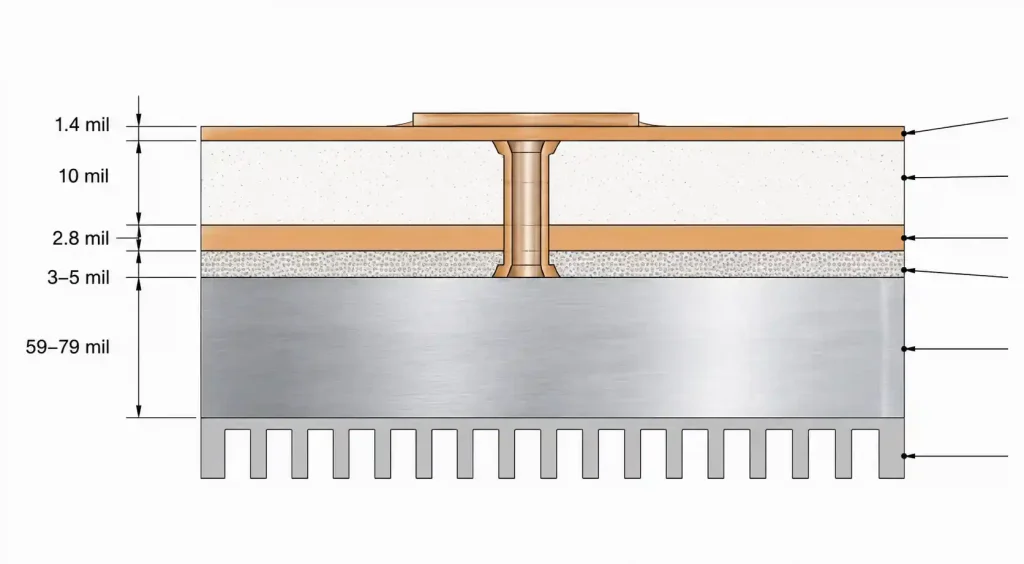
The metal core is 1.0–3.0mm aluminum alloy, 160–180 W/m·K thermal conductivity, roughly 500 times higher than FR4. A thermally conductive adhesive layer (1.0–3.0 W/m·K) bonds the Rogers sheet to the aluminum. RF signals stay on the low‑loss material, while heat dumps straight down to the heatsink. With 40‑80W dissipated in a 20mm×20mm PA footprint, we consistently measure junction temperatures under 125°C.
Rogers 4350B Material Properties vs. Competitors
| Material Property | Rogers 4350B | FR4 | Rogers 4003C | Isola I‑Tera MT40 |
|---|---|---|---|---|
| Dk @ 10GHz | 3.48±0.05 | 4.2–4.6 | 3.38±0.05 | 3.45±0.05 |
| Df @ 10GHz | 0.0037 | 0.015–0.020 | 0.0027 | 0.0038 |
| Thermal Cond. (W/m·K) | 0.69 (Z‑axis) | 0.3 | 0.64 | 0.54 |
| Tg (°C) | 280+ | 130–170 | >280 | 180 |
| CTE (ppm/°C) | 32 (X/Y), 46 (Z) | 14–17 (X/Y), 70 (Z) | 11 (X/Y), 46 (Z) | 14 (X/Y), 45 (Z) |
| Moisture Absorption (%) | 0.06 | 0.15–0.25 | 0.02 | 0.09 |
4350B offers the best cost‑performance balance for 5G sub‑6GHz and mid‑band mmWave. It processes on standard FR4 equipment, much easier than PTFE. The tight Dk tolerance ±0.05 means that as long as the fabricator holds dielectric thickness within ±10%, you get impedance control to ±2Ω.
Design Rules for 5G RF Circuits (28GHz Example)
A typical 4‑layer stackup: top layer 0.5oz copper for RF, 10mil Rogers 4350B dielectric, layer‑2 1oz copper ground plane, then 3‑5mil thermal adhesive, and finally 1.5‑2.0mm aluminum core. Thermal vias connect layer‑2 ground to the metal core.
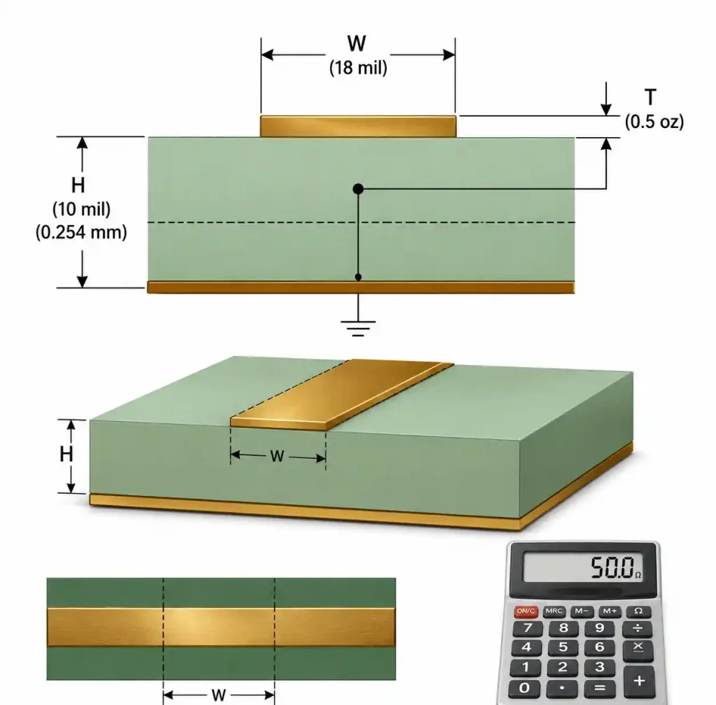
For 50‑ohm microstrip with 10mil substrate and Dk=3.48, trace width calculates to 18.2mil. At 28GHz, specify RTF or HVLP copper with Ra < 2μm – otherwise conductor loss creeps up.
| Design Parameter | Sub‑6GHz | Mid‑band mmWave (24‑28GHz) | High‑band mmWave (37‑39GHz) |
|---|---|---|---|
| Min Trace Width (mils) | 5 | 4 | 4 |
| Min Trace Spacing (mils) | 5 | 4 | 4 |
| Impedance Tolerance | ±10% | ±5% | ±5% |
| Via Diameter (mils) | 12 | 10 | 8 |
| Thermal Via Pitch (mm) | 1.5 | 1.0 | 1.0 |
| RF Trace to Ground Gap (mils) | 15 | 10 | 8 |
Check with your fabricator that they have experience with Rogers – it’s brittle and requires slower drilling speeds. For differential pairs, keep spacing equal to trace width for tight coupling.
Thermal Management – Via Stitching and Metal Core Interface
Thermal vias are the key to moving heat from RF components down to the metal core. For a 60W PA in a 15mm×15mm BGA, we typically put 100‑150 vias (12mil diameter) right under the thermal pad. Each via conducts about 0.4‑0.6W depending on plating thickness. Fill the vias with conductive epoxy or cap and plate over to prevent solder wicking.
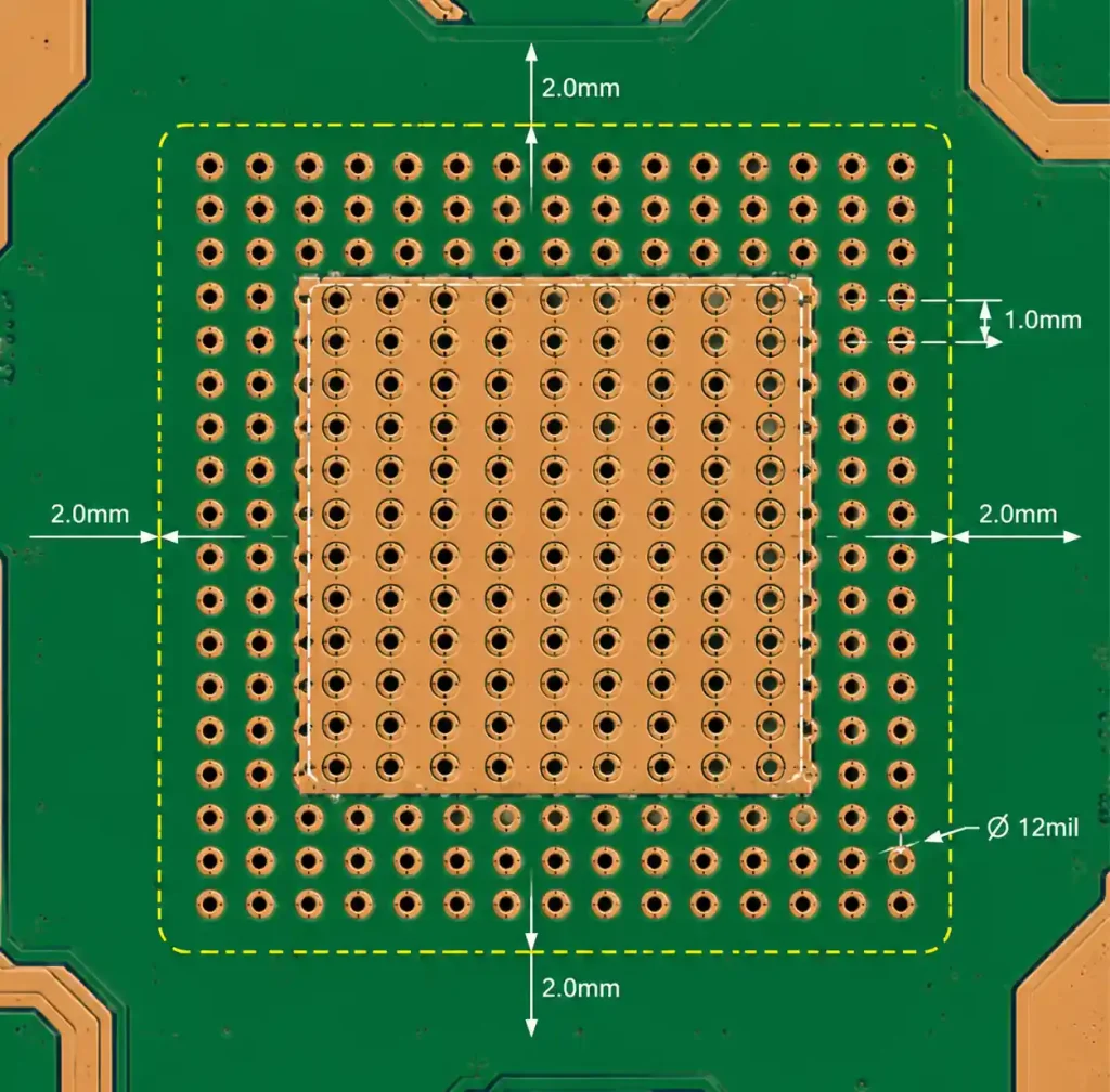
Extend the via array 2mm beyond the component outline for lateral heat spreading. Maximise copper area on layer‑2 ground plane around high‑power zones.
Via pitch matters more than diameter – shrinking pitch from 2.0mm to 1.0mm lowers junction‑to‑case resistance by 30‑40%, while increasing diameter from 12 to 20mil gives only 15‑20% improvement. The thermal adhesive (3‑5mil thick, 1.0‑3.5 W/m·K) needs higher‑grade material when PA dissipation exceeds 80W.
Impedance Verification and DFM Pitfalls
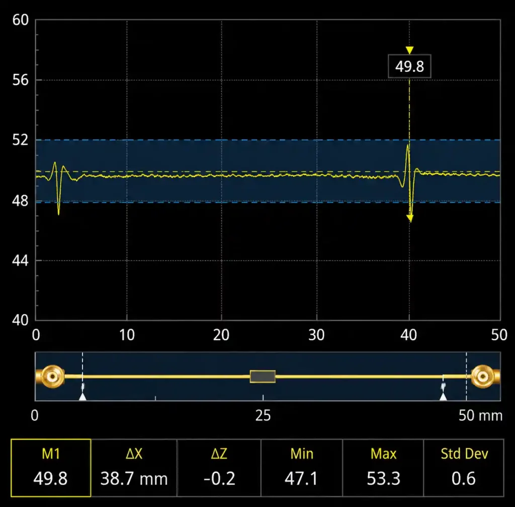
Controlled impedance depends on precise dielectric thickness, copper weight, and trace width – you need ±5% tolerance. Rogers 4350B comes in 2, 3, 5, 10, and 20mil thicknesses. For 28GHz, 10mil works well because the 18mil trace width is easy to manufacture. Fabricators build test coupons on each panel and measure with TDR or VNA.
Common manufacturing issues we see:
- Delamination at the Rogers‑adhesive interface – usually from insufficient surface prep on the aluminum.
- Via cracking – caused by dull drill bits, especially for holes below 12mil.
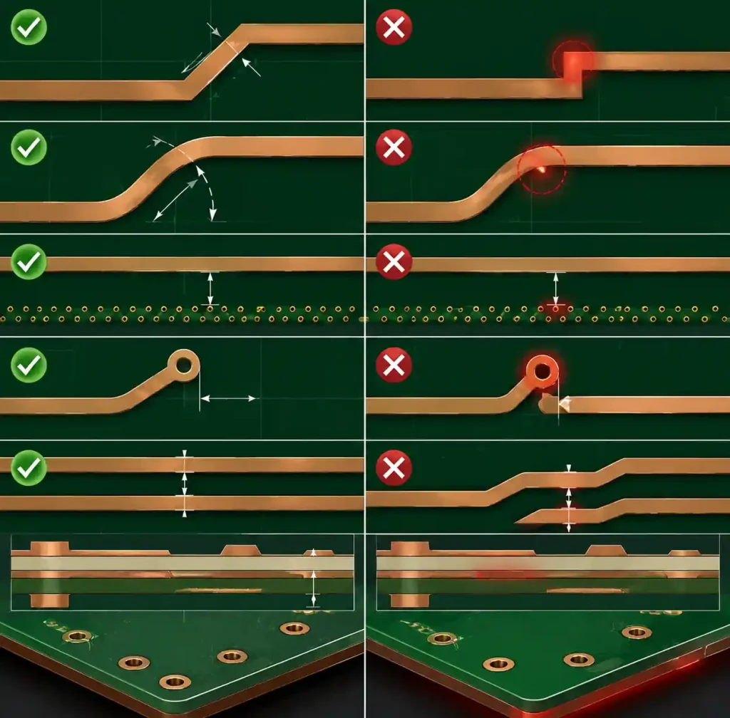
- Copper peel at sharp corners – keep bend radius at least 3× trace width.
- Metal core warpage from CTE mismatch – boards over 150mm×150mm can bow 0.5‑1.0mm.
- Solder wicking into unfilled vias – always specify filled and capped in high‑power areas.
Real‑World 5G Base Station Applications
Massive MIMO Active Antenna Systems: 64T64R or 128T128R arrays use Rogers 4350B for the RF front‑end boards with PAs, LNAs, and phase shifters. Each PA dissipates 5‑10W, total heat 500‑1000W. The metal core PCB bonds directly to the antenna backplane with forced‑air or liquid cooling.
Remote Radio Heads (RRH): Modules at 3.5GHz or 28GHz pack transceivers, PAs, and filtering into a small tower‑mounted enclosure. The metal core provides both heat conduction and structural rigidity – it acts as the heatsink itself.
Small Cells: These run 20‑40W transmit power on boards under 100mm×150mm. Bolting directly to the enclosure cuts junction‑to‑ambient resistance by 40% compared to FR4 with an add‑on heatsink.
FAQ
Q: What is the maximum frequency for Rogers 4350B?
The datasheet qualifies it to 40GHz – it handles sub‑6GHz, 24‑29GHz mid‑band, and 37‑39GHz high‑band just fine. Above 40GHz you should consider Rogers 3003 or PTFE laminates.
Q: Can I mix FR4 and Rogers 4350B in one stackup?
Yes – hybrid stackups save cost. Use Rogers 4350B for the top RF layers and FR4 for inner power/ground planes. Just confirm press cycle compatibility; Rogers 4350B needs lower pressure than FR4 to avoid shifting.
Q: How many thermal vias does a 60W PA need?
Targeting 1.0°C/W junction‑to‑case, you need roughly 120 vias of 12mil diameter (through 10mil Rogers plus adhesive). Each via has thermal resistance about 50°C/W – use N = P × Rth_target / Rth_via.
Q: Which surface finish is best for RF pads?
ENIG gives a flat surface for impedance control and good solderability. Keep nickel thickness 3‑5μm – thicker layers increase magnetic loss at high frequency. Immersion silver is cheaper but has shorter shelf life.
Q: Does Rogers 4350B require special storage?
Store in sealed bags with desiccant. If exposed more than 7 days, bake at 105°C for 2 hours before bonding to the metal core. Moisture absorption is only 0.06%, much lower than FR4, but don’t ignore it.
Conclusion and Recommendations
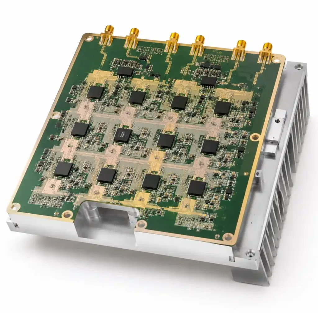
Rogers 4350B metal core PCB delivers the RF performance and thermal handling that 5G base stations demand – from 3.5GHz all the way to 39GHz. Three things to remember: get your stackup impedance calculations right, size thermal vias based on real power dissipation, and talk to your fabricator early about Rogers‑specific DFM rules. For applications with extreme power density, comparing aluminum PCB vs metal core PCB helps clarify which thermal solution fits your design. And when designing high‑density interconnect layers with fine vias, following blind and buried via design rules ensures your thermal via arrays stay reliable through reflow and thermal cycling.
We offer a free impedance calculator and thermal via spreadsheet – download them from our site. You can also upload Gerber files for a complimentary DFM review by our CAM engineers; they’ll catch Rogers‑related issues before you commit to production.