
Industrial Control PCB: Rugged Design for Harsh Environments
Industrial control systems face temperature swings from -40°C to +85°C, continuous vibration, chemical exposure, and moisture that destroy consumer electronics within months. We’ve manufactured PCBs for industrial automation, power distribution, and process control where design choices determine whether systems run 20 years or fail fast.
If you design industrial control PCBs for factory floors, outdoor enclosures, or chemical plants, you need environmental protection strategies and reliability testing beyond consumer-grade approaches. This guide covers design principles that deliver rugged industrial PCBs.
What is Industrial Control PCB?
Industrial control PCB is a circuit board engineered for PLCs, motor drives, HMIs, and automation equipment in harsh environments. These boards withstand extended temperature ranges, mechanical stress, electrical transients, and contamination that disable standard PCBs.
While consumer electronics target 3-5 year lifecycles, industrial control systems require 15-25 year lifespans. This demands 2-4oz copper, 2.0-3.2mm substrates, high-Tg materials (170-180°C), and protection layers consumer products skip. Specify these for automation, building management, energy infrastructure, and water treatment where downtime costs thousands hourly.
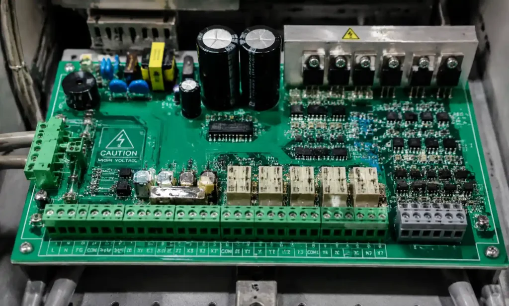
Environmental Challenges in Industrial Settings
Wide Temperature Operation
Outdoor installations swing from -40°C to +70°C. Indoor equipment creates 100°C hot spots near power components. Temperature cycling causes CTE mismatch between copper (17 ppm/°C) and FR4 (14-17 ppm/°C), leading to via cracking and solder joint failure over 10 years.
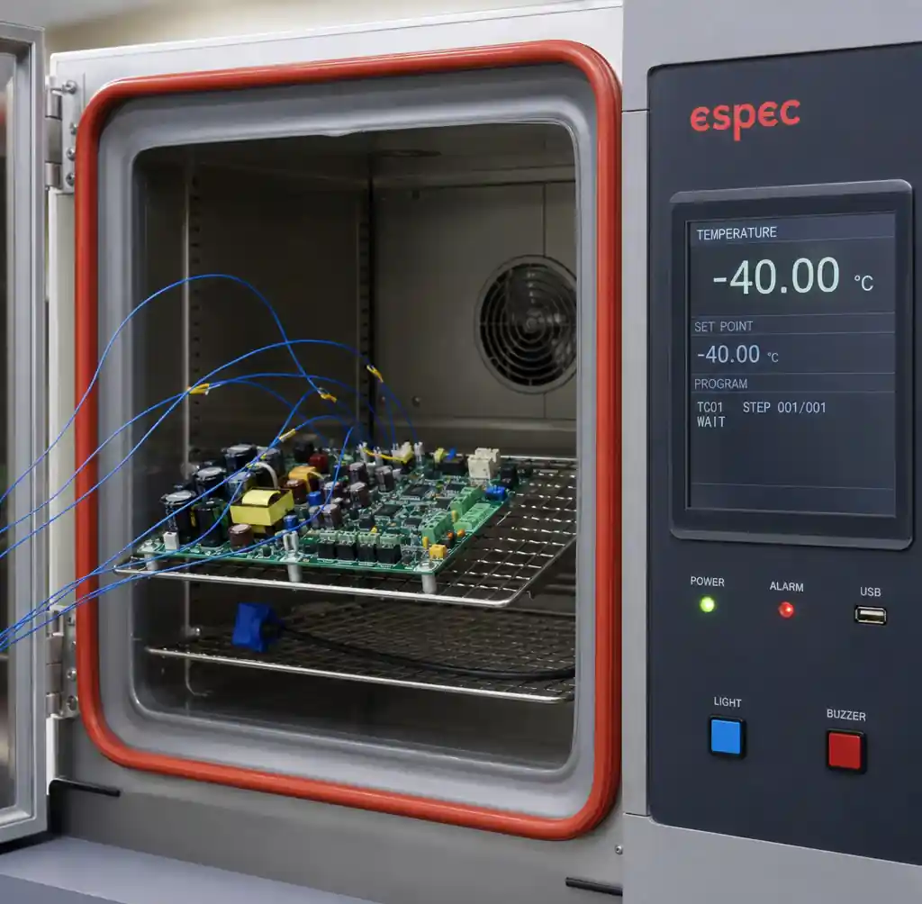
High-Tg materials (170-180°C) maintain stability 30-40°C above standard FR4 (130-140°C), preventing warpage. Testing per IPC-9701 requires 500-3000 thermal cycles. Industrial boards pass 1000+ cycles versus 200-500 for consumer electronics.
Vibration and Mechanical Stress
Industrial motors generate 10-100 Hz vibration at 2-10G acceleration. A 50g transformer at 5G creates 250g force on solder joints. Without support, fatigue cracks appear within 6-12 months.
Countermeasures include 2.4-3.2mm substrates (vs 1.6mm), mounting holes for <100cm² unsupported area, 2-4oz copper increasing pad strength 40-60%, component staking for parts >20g, and conformal coating adding 20-30% mechanical support. IEC 60068-2-64 testing simulates 10-2000 Hz vibration.
Chemical Exposure and Contamination
Chemical plants and food processing expose PCBs to acids, alkalis, and corrosive gases. Sulfur gases attack copper traces, creating copper sulfide that increases resistance. Humidity plus contamination creates conductive paths causing short circuits.
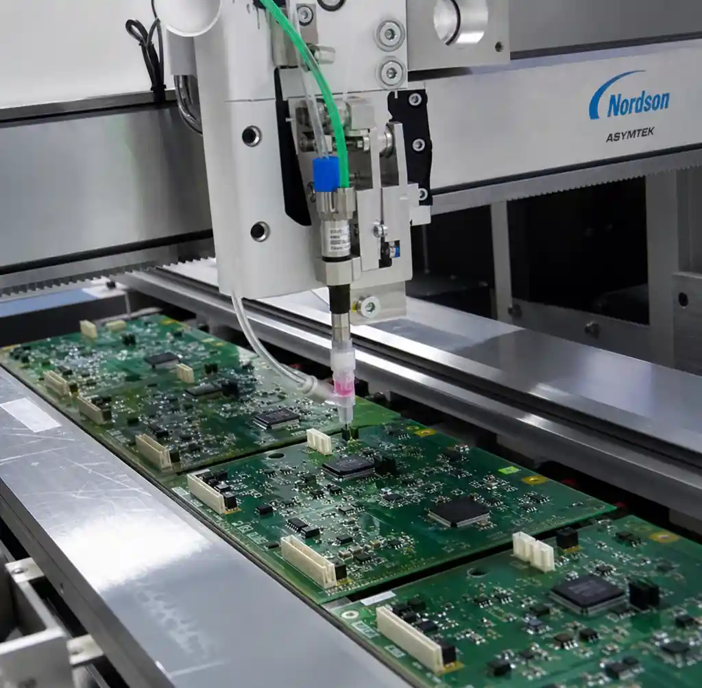
IP65/IP67 enclosures provide primary protection, but PCB conformal coating adds redundancy. Coating creates 25-125μm barriers against moisture and chemicals:
| Coating Type | Chemical Resistance | Temperature Range | Removal for Rework | Best Application |
|---|---|---|---|---|
| Acrylic (AR) | Moderate | -40°C to +125°C | Easy (solvents) | General industrial, light contamination |
| Urethane (UR) | Excellent | -40°C to +125°C | Difficult (grinding) | Chemical processing, outdoor |
| Silicone (SR) | Good | -55°C to +200°C | Difficult (mechanical) | High temperature, automotive |
| Parylene (XY) | Excellent | -65°C to +220°C | Very difficult (plasma) | Medical, aerospace, extreme environments |
Design Strategies for Extended Reliability
High-Tg Materials and Copper Weight
Standard FR4 (Tg 130-140°C) loses 50% flexural strength above glass transition. Industrial specs require high-Tg materials (170-180°C) preventing warpage near power components at 80-100°C.
Standard 1oz (35μm) copper carries ~1A per mm width at 10°C rise. Industrial boards handling 5-20A require 2-4oz copper (70-140μm) for reduced heating. Heavier copper increases via reliability—0.3mm via with 1oz copper has 25μm barrel thickness cracking within 500 cycles. 2oz copper yields 50μm thickness, doubling life to 1000+ cycles.
Creepage and Clearance for High Voltage
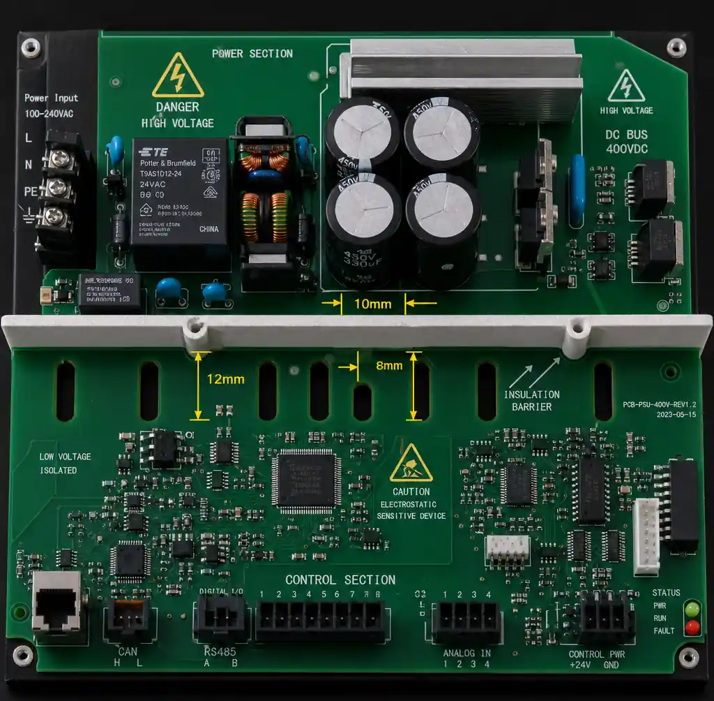
Industrial systems interface with 230-480VAC power, 600-1000VDC motor drives, and 2.5-4kV isolation circuits. IPC-2221 specifies minimum conductor spacing:
| Voltage (VAC) | Clearance (B1/B2) | Creepage (Material Group IIIa) | Application Example |
|---|---|---|---|
| 50-150V | 0.4-1.5mm | 0.8-2.5mm | 24-120VAC control circuits |
| 151-300V | 1.5-3.2mm | 2.5-5.0mm | 230VAC mains input |
| 301-600V | 3.2-6.4mm | 5.0-10.0mm | 480VAC three-phase power |
| 601-1000V | 6.4-12.7mm | 10.0-20.0mm | Motor drive DC bus isolation |
Routing slots between voltage sections increase creepage—1mm slot adds 2mm creepage (down-across-up) versus 1mm surface distance.
Robust Connector Selection
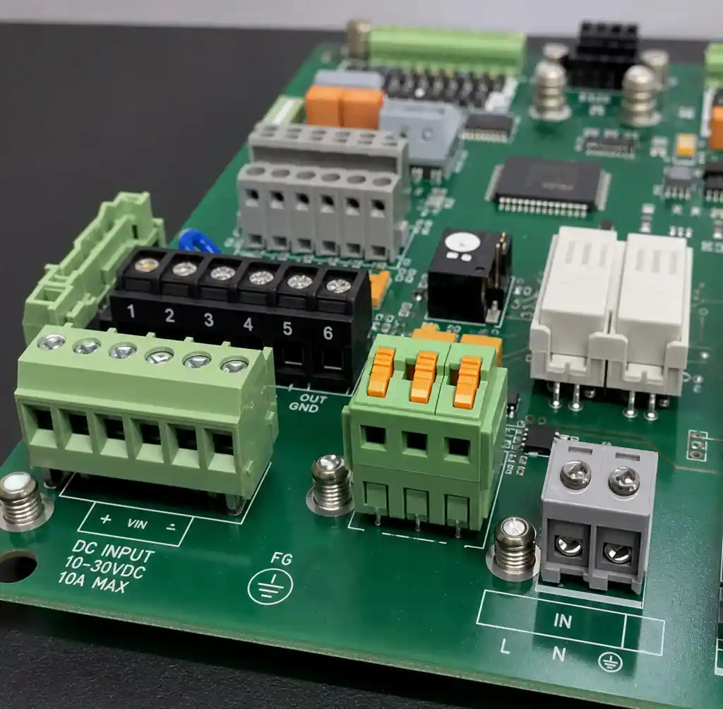
Connector failures cause 30-40% of industrial field failures. Spring-cage connectors (Phoenix Contact, Weidmüller) maintain contact force through vibration better than screw terminals. Gold-plated contacts resist corrosion versus tin-plated contacts developing oxide layers.
Through-hole connectors withstand 3-5X more pull force than SMT. A through-hole connector with 2.0mm pins through 2.4mm PCB with 2oz copper resists 40-60N versus 10-15N for SMT.
Thermal Management Integration
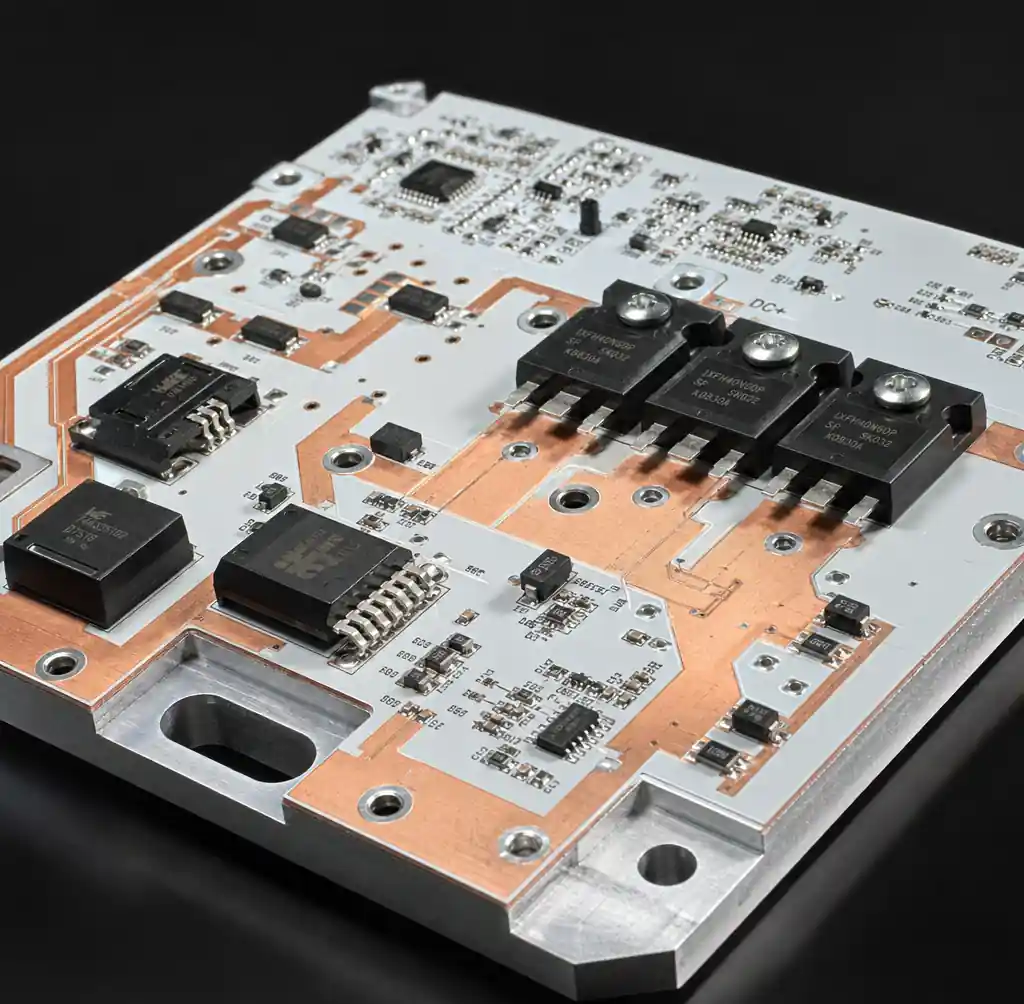
Industrial PCBs dissipate 10-100W in motor drives and power supplies. Without thermal management, junction temperatures exceed 125°C ratings, reducing lifetime 50% per 10°C increase.
Metal core PCBs with aluminum substrates (1-3 W/mK) reduce junction temperature 20-30°C versus FR4 (0.3 W/mK). For 5W MOSFETs, metal core maintains 85°C versus 115°C on FR4. Heavy 4oz copper planes improve heat spreading 35-40%. Thermal vias (0.3mm, 20-40/cm²) conduct heat to internal planes or metal substrates.
Testing and Qualification Standards
IPC-6012 Class 3 Requirements
IPC-6012 Class 3 defines acceptance for high-reliability electronics including industrial control, medical, and aerospace. Class 3 exceeds Class 2 (consumer electronics):
- Via fill: 75% minimum versus no requirement for Class 2
- Annular ring: 50μm minimum versus 0μm (breakout allowed) for Class 2
- Conductor spacing: ±20% tolerance versus ±30% for Class 2
- Hole wall: No cracks allowed versus limited acceptance for Class 2
Class 3 costs 15-25% more but field failure rates drop 60-70%.
Temperature Cycling and HALT Testing
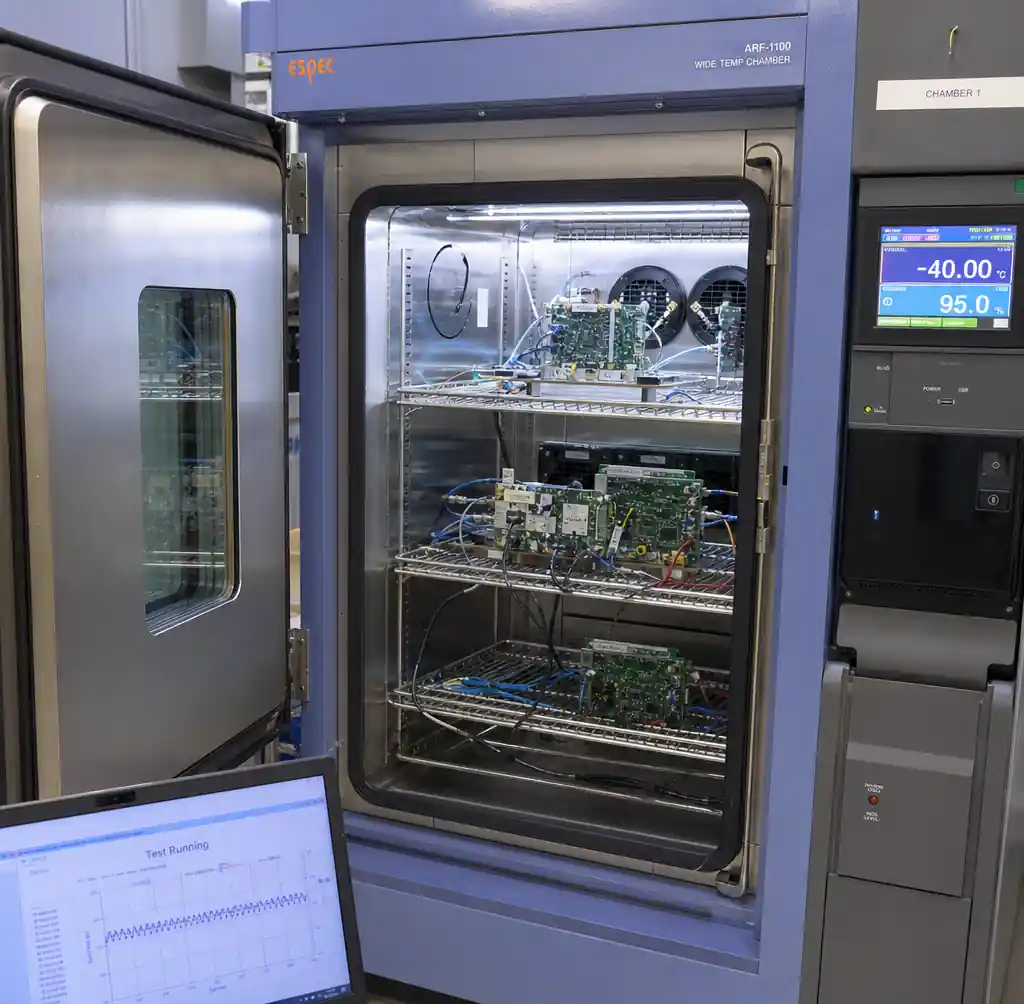
IPC-9701 temperature cycling subjects assemblies to -40°C to +85°C with 15-minute dwells. 1000 cycles simulates ~10 years of daily swings. Daisy-chain pattern monitoring detects via and solder failures early.
HALT (Highly Accelerated Life Testing) ramps temperature 30-60°C/minute with vibration, finding failure thresholds. Products surviving -55°C to +95°C in HALT operate reliably across -40°C to +85°C specs.
Environmental Testing Requirements
Tests simulating installation environments include salt spray (IEC 60068-2-52, 48-96 hours), dust ingress (IEC 60529 IP5X/IP6X), water ingress (IEC 60529 IPX4-IPX7), shock (IEC 60068-2-27, 50-100G), and EMC immunity (IEC 61000-4-x).
Long Product Lifecycle Design
Component Obsolescence Management
Industrial products serve 15-25 years while semiconductors last 5-10 years. Strategies include specifying automotive-grade components with 15+ year commitments, using standard interfaces (RS-485, Modbus, Ethernet/IP), avoiding single-source parts, and tracking end-of-life announcements.
Design for Manufacturability
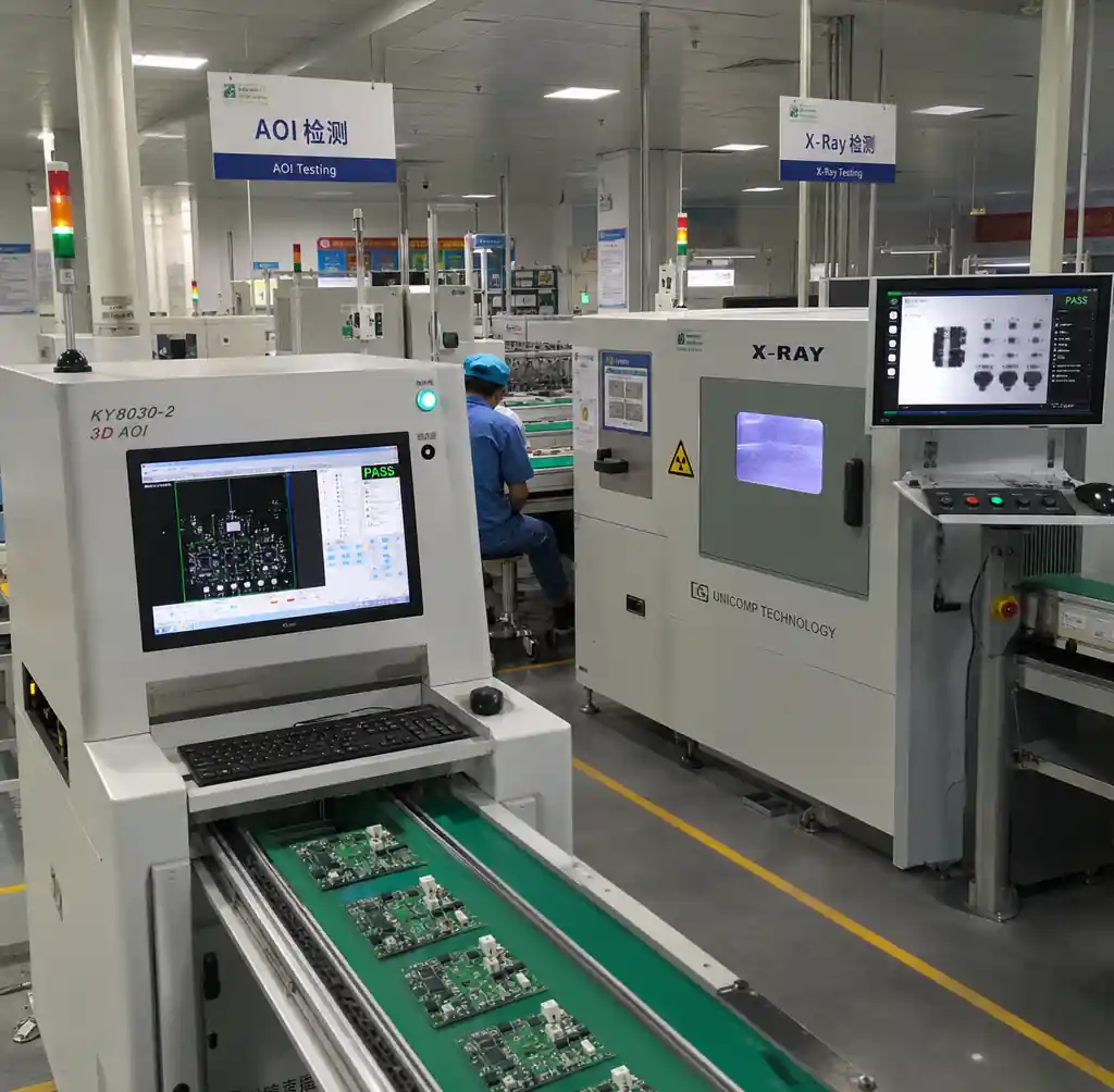
DFM rules for 10-20 year production spans include 6mil minimum trace/spacing (vs 4-5mil consumer), 0.3mm minimum via with 0.15mm annular ring, >3mm component spacing for AOI, panel fiducials for assembly calibration, and test points on 100mil grid.
Andwin Circuits manufactures industrial control PCBs up to 50 layers with 2-6oz copper, high-Tg materials (170-180°C), and IPC-6012 Class 3 certification. Our ISO 9001 and IATF 16949 facility ensures consistent manufacturing across multi-year runs.
Frequently Asked Questions
What temperature range should industrial control PCBs handle?
Industrial PCBs operate -40°C to +85°C for most equipment. Outdoor installations may need -55°C to +95°C. Use high-Tg materials (170-180°C) and verify components exceed operating range by 20-30°C margin.
Which conformal coating is best for industrial applications?
Urethane (UR) provides best balance of chemical resistance, moisture protection, and durability. Silicone (SR) handles high temperatures better near motors. Parylene (XY) offers maximum protection but costs 3-5X more.
How thick should industrial PCBs be?
Standard industrial PCBs use 2.4mm or 3.2mm versus 1.6mm consumer boards. Thicker substrates resist vibration flexing and accommodate 2-4oz copper. Power electronics with metal core use 1.6-2.0mm due to aluminum base limits.
What copper weight is required for industrial control boards?
2oz (70μm) copper is standard, providing 2X current capacity versus 1oz consumer boards. Power sections >5A require 3-4oz copper. Via reliability improves proportionally—2oz copper doubles thermal cycling life versus 1oz.
How long should industrial PCBs last?
Industrial equipment targets 15-25 year lifespans with 90-95% uptime. High-Tg FR4, heavy copper, IPC Class 3 manufacturing, conformal coating, and 1000+ cycle testing ensure full lifetime reliability.
What IP rating does a PCB need?
Enclosures provide IP ratings, not PCBs. IP65 protects against dust and water jets for indoor applications. IP67 withstands temporary immersion for outdoor environments. Add conformal coating regardless for redundant protection.
Conclusion
Industrial control PCB design prioritizes 20-year reliability over cost. High-Tg materials, heavy copper, conformal coatings, and robust connectors address temperature extremes, vibration, and contamination destroying consumer boards within months. IPC-6012 Class 3 manufacturing and environmental testing verify industrial durability.
If you need industrial control PCBs for automation, power distribution, or process control, Andwin Circuits manufactures boards up to 50 layers with heavy copper, high-Tg materials, and IPC Class 3 certification. Our ISO 9001 and IATF 16949 facility delivers reliable PCBs for 15-25 year lifecycles with fast turnaround.
Contact us today for custom industrial PCB solutions built to survive your harshest operating environments.