Introduction You are pushing more power through smaller footprints, and your components are overheating. When standard FR4 fails to dissipate heat, hardware engineers face a critical crossroad: stick with a familiar Metal Core PCB (MCPCB) or justify the premium cost of a Ceramic PCB. Making the wrong choice leads to either cracked solder joints in the field or a blown manufacturing budget.
In this guide, we bypass the marketing fluff and dive straight into the engineering data. You will learn the exact thermal thresholds (W/m·K), Coefficient of Thermal Expansion (CTE) limits, and junction temperature tipping points that dictate when to upgrade to ceramic, and when a well-designed aluminum board is perfectly sufficient.
In industries like Electric Vehicles (EV), aerospace, and high-power LED lighting, managing junction temperature is non-negotiable. Every 10°C drop in operating temperature can effectively double the Mean Time Between Failures (MTBF) of your semiconductor devices.
While standard FR4 acts as a thermal insulator (around 0.25 W/m·K), both Metal Core and Ceramic PCBs are designed to pull heat away from critical components. However, they achieve this through fundamentally different architectures. The decision between them isn’t just about “which is cooler”—it is about balancing thermal conductivity, mechanical durability, and manufacturing ROI.
2. Core Concepts Simplified
To make an objective decision, we must translate complex material science into practical layout considerations. Here are the three pillars of thermal PCB design, explained simply.
Thermal Conductivity (The Heat Highway)
Measured in Watts per meter-Kelvin (W/m·K), this dictates how fast heat travels through the board.
Analogy: Think of thermal conductivity as the speed limit on a highway. MCPCBs offer a solid 60 mph highway (1 to 4 W/m·K, sometimes up to 8 W/m·K for premium dielectrics). Ceramic PCBs, specifically Aluminum Nitride (AlN), are the Autobahn, allowing heat to travel at speeds up to 170 W/m·K.
Coefficient of Thermal Expansion (The Expanding Bridge)
CTE measures how much a material expands as it heats up.
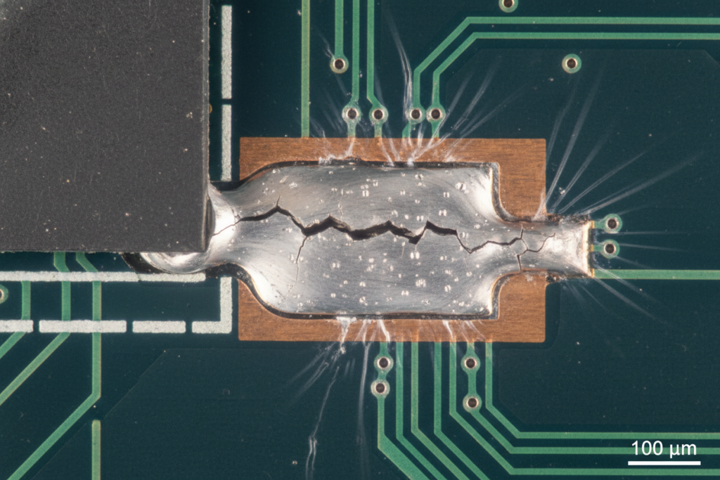
Analogy: Imagine a concrete bridge with metal joints. If the metal expands faster than the concrete in the summer heat, the joints break. In PCBs, if your board expands (high CTE) faster than the silicon chip soldered to it (low CTE), the solder joints will shear and crack under thermal cycling. Ceramics have a CTE almost identical to silicon bare dies.
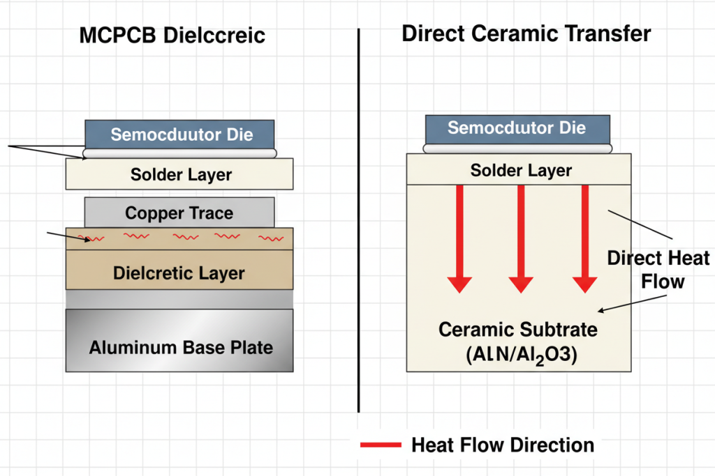
The Dielectric Layer (The Toll Booth)
In an MCPCB, you cannot place copper traces directly on the aluminum base, or it will short circuit. You need an electrically insulating layer in between.
Analogy: This dielectric layer is a toll booth on your heat highway. Even if the aluminum base can handle massive heat, if the dielectric layer is cheap and thermally resistive, the heat gets trapped at the component level. Ceramic PCBs do not have a dielectric layer; the ceramic material itself is both the electrical insulator and the thermal conductor.
Concept Comparison Table
Feature
Aluminum MCPCB
Alumina Ceramic (Al2O3)
Aluminum Nitride (AlN)
Thermal Conductivity
1 – 8 W/m·K (Dielectric limited)
24 – 30 W/m·K
140 – 170 W/m·K
CTE Match to Silicon
Poor (~22 ppm/°C)
Excellent (~7 ppm/°C)
Perfect (~4.5 ppm/°C)
Dielectric Layer Needed?
Yes (Thermal bottleneck)
No
No
Mechanical Strength
High (Rugged, bendable)
Low (Brittle, cracks easily)
Low (Brittle)
Cost Profile
Low to Medium
High
Very High
3. The Tipping Point: Step-by-Step Selection Guide
When do you actually need to spend the budget on ceramics? Let’s break down the exact thresholds.
3.1 Scenario A: High-Power LEDs & Standard Automotive
If you are designing street lighting, automotive headlights, or standard power converters, an MCPCB is usually your most cost-effective choice.
The thermal load here is high, but it is distributed. As long as your junction temperatures remain below 120°C, investing in reliable Metal Core PCBs with a quality dielectric layer (2-4 W/m·K) will provide excellent ROI. Furthermore, MCPCBs are mechanically rugged. They can withstand the heavy vibration of an automotive chassis without cracking.
If your design requires routing complexity that a single layer cannot handle, you can explore 2-layer aluminum PCB manufacturing, though you must account for the added thermal resistance of the extra prepreg layers.
3.2 Scenario B: Bare Die Packaging, Aerospace & High-Frequency RF
You must upgrade to Ceramic PCBs when you hit specific “tipping points” where MCPCBs physically fail.
Bare Die / Wire Bonding: If you are mounting silicon or SiC (Silicon Carbide) dies directly to the board, the CTE mismatch of an aluminum board will tear the wire bonds apart during thermal cycling. Ceramic is mandatory here.
Extreme Heat Density: If your component generates massive heat in a tiny footprint (e.g., high-power laser diodes, concentrated solar cells), the dielectric layer of an MCPCB will melt or degrade. You need the 170 W/m·K conductivity of AlN.
High-Frequency Performance: Ceramics offer incredibly stable dielectric constants (Dk) and low dissipation factors (Df) at high frequencies (up to 100 GHz), making them ideal for radar and RF applications where metal cores would cause signal loss.
For high-current applications where heat is an issue but CTE is not, you might also find yourself comparing differences in thermal management between Heavy Copper PCBs and Ceramics.
Engineering Specification Thresholds (When to Switch)
Application Metric
Stick with MCPCB if…
Upgrade to Ceramic if…
Component Heat Flux
< 10 W/cm²
> 15 W/cm²
Operating Temperature
Up to 130°C
150°C to 350°C+
Component Packaging
SMD / Through-hole
Bare Die / Wire Bonding
Operating Frequency
Standard Power / Low RF
Microwave / High RF (>10 GHz)
Vibration Environment
High (Automotive, Industrial)
Low/Isolated (or carefully mounted)
4. Expert Tips & Common Pitfalls to Avoid
Browsing through engineering forums like EEVblog or Reddit’s r/PrintedCircuitBoard reveals a trail of expensive mistakes made by designers transitioning between these materials. Here is the hard-earned field experience you need to know.
Pitfall 1: Treating Ceramic Like FR4 During Assembly
Ceramics (both Alumina and AlN) are essentially advanced glass. They are incredibly brittle.
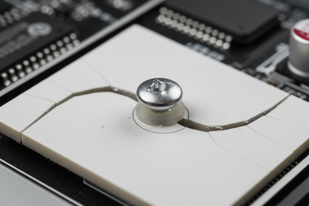
The Mistake: Engineers design a ceramic board using standard V-scoring or routing techniques, and assembly houses over-torque the mounting screws. The board cracks instantly.
The Fix: Use laser cutting for ceramic profiling. When mounting, always use soft thermal pads, nylon washers, or specialized dampening standoffs to isolate the ceramic from chassis vibrations.
Pitfall 2: Falling for “Cheap” MCPCB Specs
Not all MCPCBs are created equal. The aluminum base is cheap, but the magic is in the dielectric.
The Mistake: Procurement buys a batch of MCPCBs based purely on price. The manufacturer uses a standard FR4 prepreg as the dielectric layer instead of a thermally conductive ceramic-filled polymer. The aluminum base stays cool, but the LEDs burn out because the heat never reaches the metal.
The Fix: Always demand the datasheet for the specific dielectric material. Ensure it is rated for at least 2 W/m·K, and verify the breakdown voltage (usually >3000V) to ensure the layer isn’t dangerously thin.
Pitfall 3: Over-Engineering with AlN
Aluminum Nitride (AlN) is the holy grail of thermal management, but it costs up to 5-10 times more than standard Alumina (Al2O3).
The Fix: Do not specify AlN unless your thermal simulation explicitly shows that 24 W/m·K (Alumina) will fail. For 80% of high-temp ceramic applications, standard Alumina is perfectly adequate and much kinder to your budget.
5. Conclusion & Final Thoughts
Choosing between a Ceramic PCB and a Metal Core PCB comes down to identifying your absolute thermal and mechanical limits.
If you are dealing with standard high-power LEDs, power converters, or environments with heavy mechanical vibration, an MCPCB is your workhorse. It is durable, cost-effective, and highly efficient when paired with a premium dielectric layer.
However, if your design pushes into the bleeding edge—incorporating bare dies, extreme heat fluxes over 15 W/cm², or high-frequency RF signals—the CTE matching and unrestricted thermal conductivity of a Ceramic PCB are not just a luxury; they are a functional necessity.
Quick Summary Matrix
Decision Factor
Metal Core PCB (MCPCB)
Ceramic PCB (Alumina / AlN)
Best Used For
LEDs, Motor Drives, Automotive
Aerospace, Bare Die, High-Power Lasers
Biggest Advantage
High durability, low cost
Perfect CTE match, extreme heat transfer
Biggest Weakness
Dielectric thermal bottleneck
Highly brittle, expensive
Verdict
The standard for 80% of high-power needs.
The ultimate solution for extreme conditions.
Stop guessing with your thermal management. Run your thermal simulations, check your junction temperatures against the thresholds provided above, and select the substrate that guarantees both performance and long-term reliability.
Cookie Consent
We use cookies to improve your experience on our site. By using our site, you consent to cookies.
Used to monitor number of Google Analytics server requests when using Google Tag Manager
1 minute
_ga_
ID used to identify users
2 years
_gid
ID used to identify users for 24 hours after last activity
24 hours
_gali
Used by Google Analytics to determine which links on a page are being clicked
30 seconds
_ga
ID used to identify users
2 years
__utmx
Used to determine whether a user is included in an A / B or Multivariate test.
18 months
__utmv
Contains custom information set by the web developer via the _setCustomVar method in Google Analytics. This cookie is updated every time new data is sent to the Google Analytics server.
2 years after last activity
__utmz
Contains information about the traffic source or campaign that directed user to the website. The cookie is set when the GA.js javascript is loaded and updated when data is sent to the Google Anaytics server
6 months after last activity
__utmc
Used only with old Urchin versions of Google Analytics and not with GA.js. Was used to distinguish between new sessions and visits at the end of a session.
End of session (browser)
_gac_
Contains information related to marketing campaigns of the user. These are shared with Google AdWords / Google Ads when the Google Ads and Google Analytics accounts are linked together.
90 days
__utmb
Used to distinguish new sessions and visits. This cookie is set when the GA.js javascript library is loaded and there is no existing __utmb cookie. The cookie is updated every time data is sent to the Google Analytics server.
30 minutes after last activity
__utmt
Used to monitor number of Google Analytics server requests
10 minutes
__utma
ID used to identify users and sessions
2 years after last activity
SourceBuster is used by WooCommerce for order attribution based on user source.
Name
Description
Duration
sbjs_migrations
Technical data to help with migrations between different versions of the tracking feature
session
sbjs_current_add
Timestamp, referring URL, and entry page for your visitor’s current visit to your store
session
sbjs_first_add
Timestamp, referring URL, and entry page for your visitor’s first visit to your store (only applicable if the visitor returns before the session expires)
session
sbjs_current
Traffic origin information for the visitor’s current visit to your store
session
sbjs_first
Traffic origin information for the visitor’s first visit to your store (only applicable if the visitor returns before the session expires)
session
sbjs_udata
Information about the visitor’s user agent, such as IP, the browser, and the device type
session
sbjs_session
The number of page views in this session and the current page path