
Ceramic PCB vs Metal Core PCB: Which Thermal Solution is Better?
Thermal management challenges account for up to 55% of electronic device failures in high-power applications. Selecting the right thermal substrate—ceramic PCB or metal core PCB—determines whether your design achieves optimal thermal performance or encounters costly failures. This guide compares both technologies across thermal conductivity, mechanical properties, cost, and real-world applications.
What is Ceramic PCB?
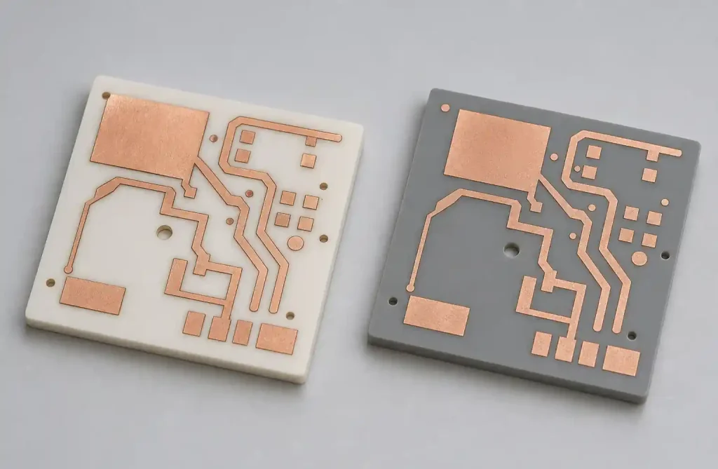
Ceramic PCB uses ceramic materials like alumina (Al₂O₃) or aluminum nitride (AlN) as the substrate instead of FR-4. Alumina offers 24-28 W/mK thermal conductivity, while AlN provides 150-170 W/mK—far exceeding FR-4’s 0.3-0.4 W/mK.
Ceramic PCBs excel in applications requiring exceptional heat dissipation, high-frequency signal integrity, and operation above 300°C. Aerospace, RF/microwave systems, high-power LED modules, and military equipment commonly use ceramic substrates.
What is Metal Core PCB?
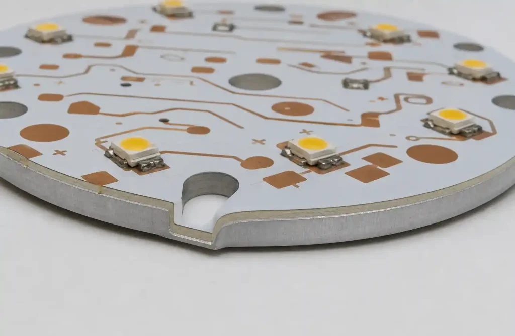
Metal Core PCB (MCPCB) uses a metal base layer—typically aluminum—as an integrated heat sink. Construction includes a copper circuit layer (1-10 oz), a thermally conductive dielectric layer (1-9 W/mK), and an aluminum base. The dielectric provides electrical isolation while allowing heat transfer to the metal core.
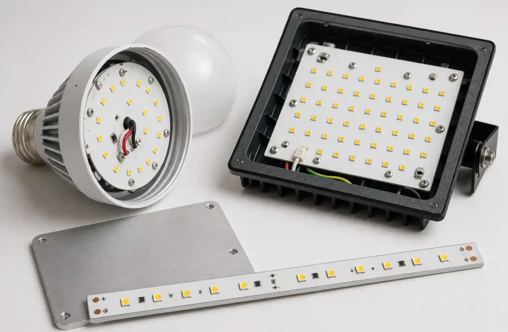
MCPCBs serve LED lighting, automotive electronics, and power supplies where cost-effective thermal management is needed without extreme performance demands.
Thermal Performance Comparison
| Parameter | Ceramic PCB (Alumina) | Ceramic PCB (AlN) | Metal Core PCB (Aluminum) |
|---|---|---|---|
| Thermal Conductivity | 24-28 W/mK | 150-170 W/mK | 1-9 W/mK (dielectric limited) |
| Base Material | 96-99.6% Al₂O₃ | Aluminum Nitride | Aluminum alloy |
| Max Operating Temp | 350°C+ | 350°C+ | 140°C (typical) |
| Thermal Expansion (CTE) | 6.5-7.2 ppm/°C | 4.5-5.7 ppm/°C | 23-24 ppm/°C |
| Dielectric Strength | 15-20 kV/mm | 14-17 kV/mm | 2-4 kV/mm |
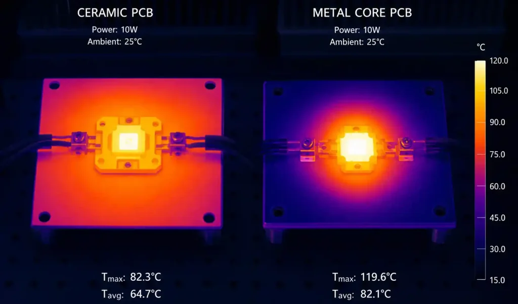
Ceramic PCBs deliver superior absolute thermal conductivity. AlN achieves 150-170 W/mK—the highest among commercial PCB substrates. MCPCBs achieve effective thermal management through the aluminum base (~200 W/mK) spreading heat laterally, but the dielectric layer limits vertical transfer to 1-9 W/mK.
Mechanical and Electrical Properties
CTE Matching: Silicon devices have CTE of 2.6-3.5 ppm/°C. Ceramic substrates (4.5-7.2 ppm/°C) match much better than aluminum MCPCBs (23-24 ppm/°C). This reduces solder joint stress during thermal cycling, extending operational lifetime in aerospace, automotive, and industrial applications.
Electrical Insulation: Ceramic provides 15-20 kV/mm dielectric strength versus MCPCB’s 2-4 kV/mm, enabling higher voltage operation and stable performance across temperature ranges.
Mechanical Rigidity: Both offer excellent rigidity. Ceramics are extremely hard with superior dimensional stability but are brittle and can fracture under impact. MCPCBs offer good rigidity with better mechanical toughness.
Cost Analysis
| Cost Factor | Ceramic PCB | Metal Core PCB |
|---|---|---|
| Raw Material | $80-$300 per board | $15-$60 per board |
| Manufacturing Complexity | High (specialized processes) | Medium (standard processes) |
| Minimum Order Quantity | Often higher MOQ | Lower MOQ available |
| Assembly Cost | Higher (specialized handling) | Standard SMT assembly |
| Total Cost Premium | 5-15× vs MCPCB | Baseline comparison |
Ceramic PCBs cost 5-15 times more than MCPCBs. Alumina costs 5-10× more than aluminum MCPCBs; AlN costs 10-15× more. Manufacturing requires specialized DBC or AMB processes with longer lead times (3-6 weeks vs 7-15 days for MCPCB).
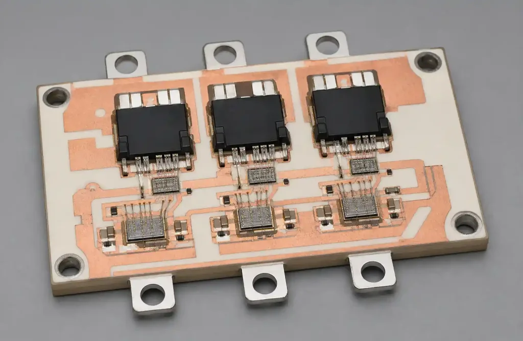
For high-volume LED lighting or consumer electronics, MCPCB offers the best cost-performance ratio. For aerospace, military, or high-reliability applications, ceramic substrates justify the premium.
Manufacturing Considerations
Ceramic PCB: Uses DBC, AMB, or thick/thin film metallization. DBC bonds copper through high-temperature oxidation. Via formation uses laser drilling. Lead times: 3-6 weeks.
MCPCB: Follows standard PCB processes with metal base lamination. Supports 1-10 oz copper, standard finishes, and conventional vias. Lead times: 7-15 days. Assembly follows standard SMT procedures.
Application-Specific Recommendations
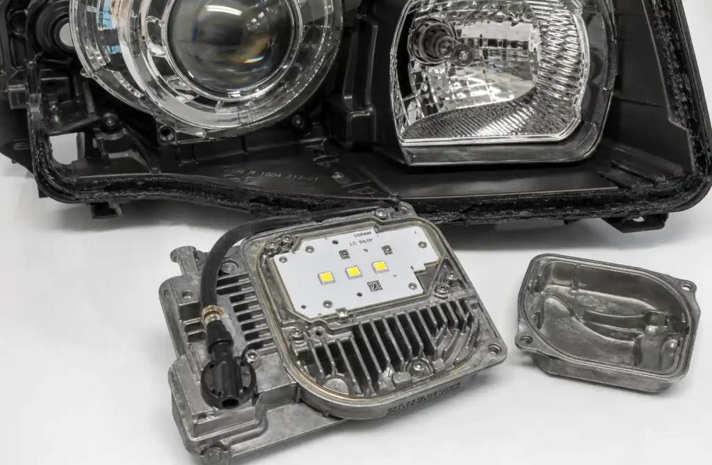
LED Lighting: MCPCB for general lighting (0.5-3W per LED); ceramic for high-power LEDs (5W+), automotive headlights, and ultra-high brightness applications.
Automotive Electronics: MCPCB for exterior lighting, power modules, and DC-DC converters. Ceramic for under-hood (>150°C), HID ballasts, EV inverters, and ADAS radar.
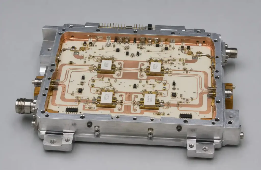
RF/Microwave: Ceramic dominates due to stable dielectric constant, low loss tangent, excellent thermal conductivity, and CTE matching with semiconductors.
Power Electronics:
| Application Type | Recommended Solution | Key Considerations |
|---|---|---|
| Low-Medium Power (<500W) | MCPCB | Cost-effective, adequate thermal performance |
| High Power (500W-5kW) | MCPCB or Ceramic | Depends on power density |
| Very High Power (>5kW) | Ceramic PCB | Superior thermal performance required |
| High Voltage (>600V) | Ceramic PCB | Better electrical isolation |
When to Choose Ceramic PCB
Choose ceramic when:
- Component junction temperatures exceed 150°C
- Power density exceeds 10W/in²
- Thermal cycling between -55°C and +200°C
- Operating voltages exceed 600V
- RF/microwave applications need stable dielectric properties
- CTE matching with semiconductors is critical
Applications: Aerospace, defense, high-power RF amplifiers, laser diode arrays, EV power inverters (>200kW), satellite systems.
When to Choose Metal Core PCB
Choose MCPCB when:
- Component temperatures remain below 120-140°C
- Heat dissipation is distributed across board area
- Cost-sensitive, high-volume production
- Standard SMT assembly without specialized handling
- 7-15 day lead times meet project schedules
Applications: LED lighting (residential, commercial, industrial), automotive interior/exterior lighting, power supplies (<500W), battery charging, motor drives.
FAQs
What is the thermal conductivity difference between ceramic and metal core PCBs?
Ceramic offers 24-28 W/mK (alumina) or 150-170 W/mK (AlN). MCPCB achieves 1-9 W/mK through the dielectric layer. The aluminum base itself has ~200 W/mK conductivity but the dielectric limits vertical heat transfer.
Can metal core PCBs handle high operating temperatures?
Standard aluminum MCPCBs operate up to 140°C, limited by the dielectric. Premium materials handle 150-180°C. Ceramic PCBs are required for applications regularly exceeding 200°C.
Why are ceramic PCBs more expensive than metal core PCBs?
Ceramic materials cost significantly more, and manufacturing requires specialized DBC/AMB processes. Fewer facilities offer ceramic capabilities. Ceramic PCBs typically cost 5-15× more than equivalent MCPCBs.
Which thermal solution is better for automotive LED headlights?
Automotive headlights increasingly use ceramic PCBs due to high power density (10-20W per LED), compact packaging, and reliability under thermal cycling. Lower-power exterior lighting uses MCPCB.
How do I calculate which thermal solution I need?
Calculate total power dissipation, junction temperature limits, and thermal resistance. If analysis shows junction temperatures exceeding 150°C with MCPCB values (1-3°C/W), ceramic is required. Otherwise, MCPCB is appropriate.
Conclusion
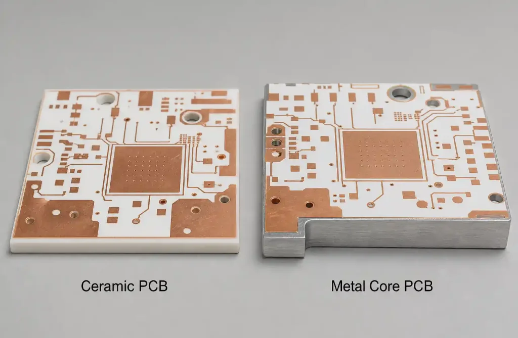
Ceramic PCBs and MCPCBs serve different thermal management needs. Ceramic substrates deliver superior thermal conductivity (24-170 W/mK), high-temperature performance, and CTE matching—essential for high-power density, extreme environments, and RF systems. MCPCBs provide cost-effective thermal management (1-9 W/mK) suitable for LED lighting, automotive, and power supplies where thermal requirements fall within their capabilities.
Choose ceramic when thermal performance, CTE matching, or electrical isolation exceeds MCPCB capabilities despite 5-15× higher cost. Choose MCPCB for high-volume applications where adequate thermal management supports competitive products.
If you need thermal management PCB solutions, Andwin Circuits offers both metal core PCB and advanced ceramic substrate capabilities with expert thermal design support, rigid flex PCB integration, and fast delivery. Certified to ISO 9001, IATF 16949, and UL standards.
Contact us today for thermal management PCB solutions and competitive factory-direct pricing.