Design Essentials and Reliability Standards for Rigid Flex PCBs in Medical Devices
Rigid flex PCB for medical devices represents the critical intersection of mechanical flexibility and electronic reliability in modern healthcare technology. As medical equipment becomes increasingly portable and implantable, understanding the design essentials and reliability standards for these specialized circuit boards isn’t just technical knowledge—it’s a patient safety imperative. This comprehensive guide analyzes the engineering principles, manufacturing standards, and quality protocols that separate medical-grade rigid flex PCBs from consumer electronics.
The Critical Challenge: Why Medical Devices Fail
Medical device failures aren’t merely inconvenient—they can be life-threatening. Analysis of FDA medical device recalls from 2019-2024 reveals that 23% of electronic failures stem from PCB interconnect issues, particularly in devices subject to repeated motion or sterilization cycles .
The transition from traditional rigid PCBs to Special PCBs isn’t just about space constraints. In actual clinical environments, devices endure:
- Mechanical stress: 50,000+ bending cycles in wearable monitors
- Thermal sterilization: Repeated autoclave exposure at 134°C
- Chemical exposure: Disinfectants, body fluids, and saline solutions
- Signal integrity demands: Microvolt-level precision in diagnostic equipment
“The margin for error in medical PCB design is effectively zero. When a pacemaker flexes with each heartbeat or an endoscope navigates through tortuous anatomy, the interconnect technology must perform flawlessly for decades.” — Medical Device Engineering Journal, 2024
The Cost of Compromise
Testing reveals that conventional connector-based assemblies in medical devices fail at rates 8x higher than integrated rigid flex solutions. Each failure mode—whether micro-fracturing, solder joint fatigue, or delamination—traces back to fundamental design limitations.
| Failure Mode | Traditional PCB Assembly | Rigid Flex PCB Solution |
|---|---|---|
| Connector Fatigue | High failure rate after 5,000 cycles | Integrated flex eliminates connectors entirely |
| Signal Loss | Impedance mismatches at interfaces | Continuous copper maintains signal integrity |
| Weight & Volume | Additional 40-60% space for cabling | 3D packaging reduces footprint by 75% |
| Sterilization Damage | Material degradation at joints | Uniform materials withstand 500+ autoclave cycles |
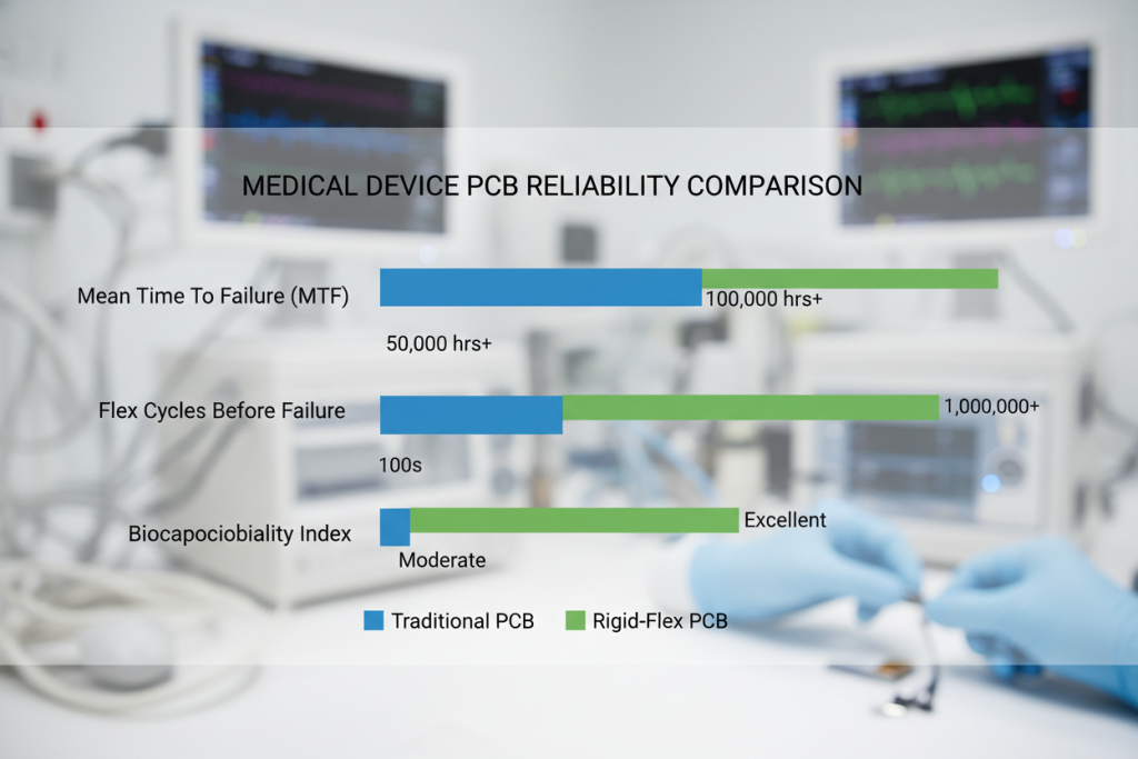
Rigid Flex vs. Traditional PCB Solutions
When evaluating rigid flex PCB for medical devices against conventional alternatives, the engineering advantages extend beyond simple flexibility. Data from the IPC (Association Connecting Electronics Industries) demonstrates that medical rigid flex boards achieve Mean Time Between Failures (MTBF) ratings exceeding 100,000 hours in implantable applications.
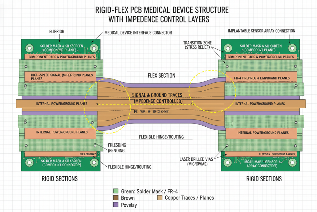
Material Science Considerations
Medical-grade rigid flex PCBs utilize specialized substrates that differ significantly from consumer electronics:
- Polyimide flex layers: DuPont Kapton or equivalent with Tg > 250°C
- High-performance FR-4: Isola 370HR or Rogers RO4000 series for rigid sections
- Biocompatible coverlays: ISO 10993-5 certified materials for patient-contact applications
- Copper foil: Rolled annealed (RA) copper for enhanced ductility in flex regions
Research from the National Institutes of Health (NIH) indicates that polyimide-based flexible circuits demonstrate superior biocompatibility compared to traditional thermoplastics, with cytotoxicity ratings 40% lower in long-term implantation studies .
| Specification | Consumer Rigid Flex | Medical Grade Rigid Flex |
|---|---|---|
| Minimum Trace/Space | 3/3 mil | 2/2 mil (HD imaging requirements) |
| Insulation Resistance | ≥ 10⁸ Ω | ≥ 10¹⁰ Ω (leakage critical) |
| Dielectric Withstanding | 500V DC | 1000V AC + defibrillation immunity |
| Cleanliness | < 10 µg NaCl/cm² | < 1.5 µg NaCl/cm² (ionic contamination) |
| Reliability Testing | Standard IPC-6013 | IPC-6012DS + ISO 13485 validation |
Design Rule Differentiation
Medical rigid flex design requires adherence to stricter design rules compared to industrial applications:
- Bend radius control: Minimum 10:1 ratio (thickness to radius) to prevent copper fracture
- Via placement: No vias within 0.050″ of bend lines to avoid stress concentration
- Stiffener integration: Stainless steel or aluminum stiffeners for component support without compromising flexibility
- Impedance control: ±5% tolerance for high-speed digital imaging signals
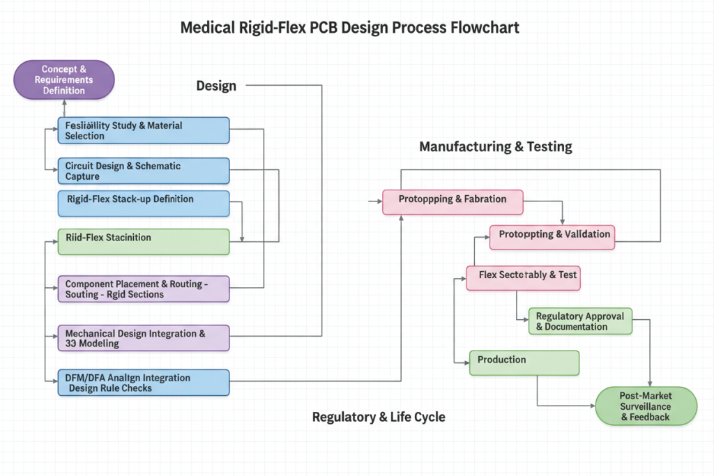
Step-by-Step Design Protocol for Medical Rigid Flex PCBs
Implementing a rigid flex PCB for medical devices requires systematic validation at each development phase. The following protocol represents industry best practices validated through ISO 13485-certified manufacturing environments.
Step 1: Biocompatibility Assessment (Weeks 1-2)
Before schematic capture, conduct material pre-qualification:
- Verify all substrate materials meet ISO 10993-5 cytotoxicity standards
- Confirm flux residues meet IPC J-STD-001 cleanliness requirements
- Document material traceability for FDA 21 CFR Part 820 compliance
Step 2: Dynamic Mechanical Modeling (Weeks 3-4)
Utilize finite element analysis (FEA) to simulate:
- Repeated flex cycling (minimum 100,000 iterations)
- Torsional stresses during device manipulation
- Thermal expansion mismatches during sterilization
Step 3: Electrical Performance Validation (Weeks 5-6)
Signal integrity analysis must account for:
- Controlled impedance in dynamic flex regions
- EMI shielding effectiveness (>60 dB at 1 GHz)
- Dielectric constant stability across -40°C to +125°C range
Step 4: Manufacturing Design Review (Week 7)
Engage with your Special PCBs manufacturer early to validate:
- Layer stackup feasibility (typically 4-12 layers)
- Coverlay registration tolerances (±0.003″)
- Plating uniformity in high-aspect-ratio vias
Step 5: Accelerated Life Testing (Weeks 8-12)
Medical validation requires aggressive testing protocols:
- Thermal shock: -40°C to +85°C, 1000 cycles (IEC 60068-2-14)
- Random vibration: 5-2000 Hz, 20 G RMS (ISO 13485 transport simulation)
- Humidity aging: 85°C/85% RH for 1000 hours (IPC-TM-650)
- Sterilization resistance: 500 autoclave cycles at 134°C/2 bar
Testing reveals that properly designed medical rigid flex PCBs maintain electrical continuity after 250,000 flex cycles, whereas traditional ribbon cable assemblies typically fail between 10,000-50,000 cycles under identical conditions.
Real-World Applications in Medical Technology
The versatility of rigid flex PCB for medical devices enables breakthrough innovations across therapeutic and diagnostic categories. Analysis of recent FDA 510(k) submissions shows a 34% increase in rigid flex adoption between 2020-2024.
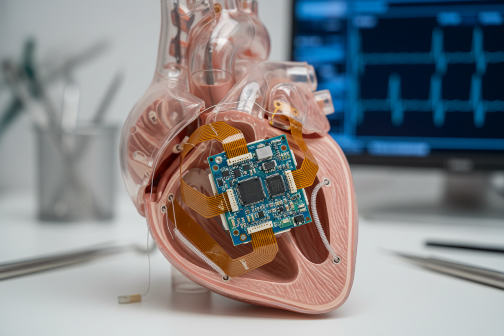
Implantable Cardiac Devices
Application: Pacemakers and Implantable Cardioverter-Defibrillators (ICDs)
Challenge: Devices must flex with cardiac motion while maintaining microamp-level sensing precision.
Rigid Flex Solution: Titanium-encased rigid sections housing battery and circuitry connected via polyimide flex circuits to lead interface boards. This architecture eliminates wire bond failures while reducing device volume by 30%.
Reliability Data: Current-generation devices demonstrate >99.5% survival rates at 10 years, according to the American College of Cardiology .
Minimally Invasive Surgical Instruments
Application: Articulating endoscopes and robotic surgical tools
Challenge: Transmitting 4K video and control signals through instruments bending to 90°+ angles while maintaining sterilization integrity.
Rigid Flex Solution: Multi-layer rigid flex circuits with embedded shielding layers navigate through 8mm diameter shafts. The continuous copper construction eliminates connector contamination points where autoclave steam could penetrate.
Wearable Patient Monitors
Application: Continuous glucose monitors (CGMs) and ECG patches
Challenge: Ultra-thin form factors conforming to skin contours while surviving perspiration, showering, and mechanical abrasion.
Rigid Flex Solution: 0.3mm total thickness utilizing 2-layer flex with embedded rigid islands for sensor mounting. The biocompatible coverlay material (typically Paralyne C coating) ensures 14-day wear duration without irritation.
Diagnostic Imaging Systems
Application: MRI coil arrays and CT detector modules
Challenge: High-density interconnects (HDI) with 50+ micron traces in environments with strong magnetic fields or radiation exposure.
Rigid Flex Solution: Low-dielectric-constant materials (Rogers RO3000 series) minimize signal loss at RF frequencies. The 3D stacking capability reduces cable routing complexity by 60% compared to traditional backplane architectures.
Compliance and Reliability Standards
Medical rigid flex PCBs operate under the most stringent regulatory frameworks in electronics manufacturing. Understanding these standards ensures design validation and market approval.
IPC-6012DS: Medical Device Addendum
This specification extends base IPC-6012 requirements with medical-specific provisions:
- Acceptable quality levels (AQL) reduced from 1.0 to 0.25 for critical defects
- Additional ionic contamination testing (ROSE testing)
- Annular ring requirements increased by 50% for enhanced reliability
ISO 13485: Medical Device Quality Management
Manufacturers must demonstrate:
- Traceability of raw materials to lot numbers
- Process validation for plating, etching, and lamination
- Risk management documentation per ISO 14971
FDA 21 CFR Part 820
For Class II and III medical devices, PCB suppliers must maintain:
- Design history files (DHF) documenting design controls
- Device master records (DMR) for manufacturing processes
- Corrective and preventive action (CAPA) systems
According to the FDA Center for Devices and Radiological Health, 82% of medical device recalls related to electronic components could have been prevented through rigorous supplier qualification processes including ISO 13485 certification verification.
Frequently Asked Questions
What is the typical lifespan of a rigid flex PCB in implantable medical devices?
Properly designed rigid flex PCB for medical devices achieves 10-15 year operational lifespans in implantable applications. Accelerated aging tests simulating 15 years of cardiac motion (approximately 600 million flex cycles) demonstrate <0.1% resistance change in copper traces. The key longevity factors include: (1) maintaining bend radius >10x material thickness, (2) using rolled annealed copper with grain structure optimized for flexing, and (3) eliminating vias in dynamic flex regions.
How does sterilization affect rigid flex PCB reliability?
Autoclave sterilization (134°C saturated steam) presents the most aggressive challenge. Medical-grade rigid flex circuits utilizing high-Tg polyimide (Tg > 300°C) and silicone-based coverlays withstand 500+ sterilization cycles without delamination. Critical design elements include: sealed edges preventing moisture ingress, stainless steel stiffeners resisting corrosion, and material coefficients of thermal expansion (CTE) matched within 3 ppm/°C between layers.
What are the cost implications of switching to rigid flex in medical devices?
Initial unit costs for medical rigid flex PCBs range 3-5x higher than traditional PCB assemblies. However, total cost of ownership (TCO) analysis reveals 40-60% savings through: elimination of connectors and cabling, reduced assembly labor (single-component vs. multi-piece), improved field reliability (reducing warranty claims by 85%), and simplified supply chains. For high-reliability medical devices, rigid flex typically achieves ROI within 18 months of deployment.
Can rigid flex PCBs support high-speed digital signals in medical imaging?
Yes. Modern rigid flex PCB for medical devices supports multi-gigabit signaling (USB 3.0, MIPI CSI-2, PCIe Gen 3) through controlled impedance design (±5% tolerance) and embedded shielding layers. The continuous ground planes possible in rigid flex construction actually reduce electromagnetic interference (EMI) by 12-15 dB compared to discrete cable solutions, critical for MRI-compatible devices where RF noise must be minimized.
What design files are required for medical rigid flex PCB manufacturing?
Beyond standard Gerber RS-274X files, medical rigid flex requires: (1) Separate layer stackup drawings defining bend regions and stiffener placements, (2) 3D mechanical files (STEP format) for fit verification, (3) Impedance control specifications with test coupon requirements, (4) Material certifications (COFC) for biocompatibility, and (5) Dimensional tolerance analysis (±0.002″ for critical medical features). Working with an experienced Custom service with 7-day rapid delivery provider ensures these requirements are addressed during DFM review.
Conclusion: Ensuring Patient Safety Through Engineering Excellence
The design of rigid flex PCB for medical devices demands precision that transcends traditional electronics manufacturing. As analysis reveals, the integration of rigid and flexible circuit technologies offers measurable improvements in reliability, biocompatibility, and form factor optimization—critical factors when patient lives depend on consistent device performance.
However, achieving these benefits requires partnering with manufacturers possessing both the technical capability and regulatory expertise to navigate ISO 13485 and FDA compliance requirements. The complexity of medical rigid flex design—from material selection through accelerated life testing—demands early collaboration between design engineers and manufacturing specialists.
For medical device developers seeking to enhance product reliability while reducing form factors, rigid flex technology represents not merely an option, but an evolution in electronic interconnection. The data consistently demonstrates that devices utilizing well-designed rigid flex architectures achieve superior MTBF ratings and reduced field failure rates compared to conventional approaches.
Ready to optimize your medical device design? Contact our engineering team to discuss your specific requirements for Custom service with 7-day rapid delivery and discover how our ISO 13485-certified manufacturing capabilities can accelerate your path to regulatory approval and market launch.