
Lightweight Design Solutions for Drone Flight Control System Hardware-Software Integrated Boards
The evolution of unmanned aerial vehicles (UAVs) has created unprecedented demand for flight control systems that balance performance, reliability, and weight efficiency. Modern drone applications—from commercial delivery services to precision agriculture and aerial cinematography—require flight control boards that deliver sophisticated functionality while minimizing payload impact. This comprehensive guide explores proven strategies for achieving lightweight design in drone flight control system PCBs without compromising performance or reliability.
Understanding Flight Control System PCB Requirements
Drone flight control boards serve as the central nervous system of UAVs, integrating sensors, processors, communication modules, and power management circuits into a single platform. The unique operational environment demands boards that withstand vibration, temperature extremes, and electromagnetic interference while maintaining minimal weight.
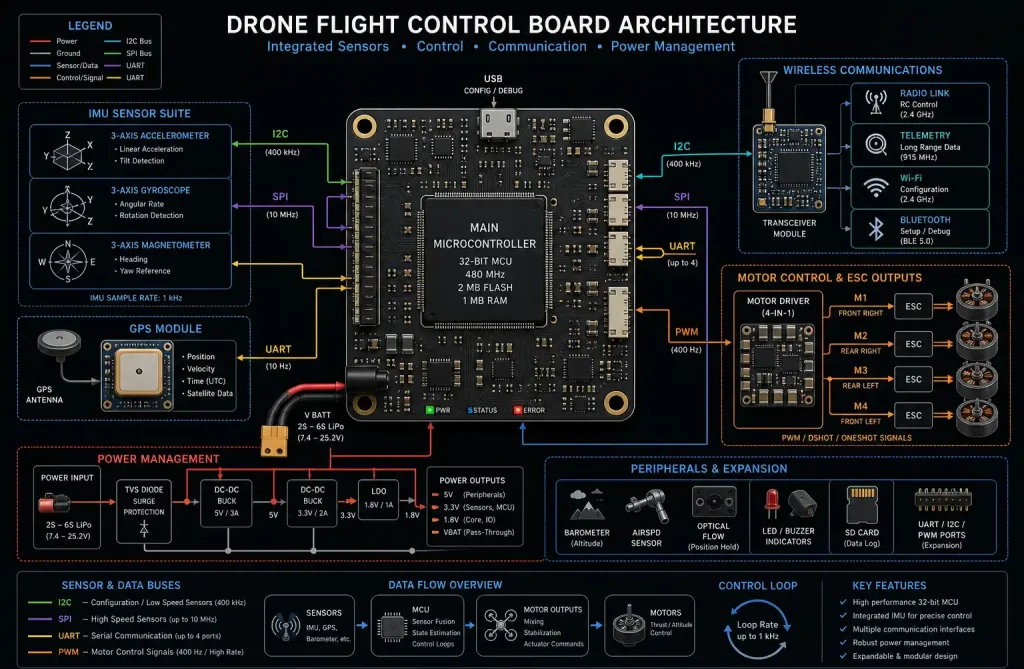
Modern flight controllers typically integrate multiple subsystems: inertial measurement units (IMUs) with accelerometers and gyroscopes, barometric pressure sensors, GPS modules, microcontrollers or processors running flight algorithms, motor control circuits, and wireless communication interfaces. Each subsystem contributes to overall board weight, making systematic optimization essential.
Weight reduction directly impacts flight time, payload capacity, and maneuverability. For commercial drones, every gram saved translates to extended operational range or increased cargo capacity. Racing drones benefit from improved acceleration and agility, while inspection drones gain longer mission durations.
Material Selection for Weight Optimization
PCB substrate material fundamentally determines board weight and performance characteristics. Traditional FR-4 remains popular for cost-sensitive applications, but advanced materials offer superior weight-to-performance ratios for demanding drone applications.
High-Performance Substrate Options:
Rogers materials (RO4003C, RO4350B) provide excellent high-frequency performance with lower dielectric constants than FR-4, enabling thinner substrates while maintaining impedance control. These materials typically weigh 15-20% less than equivalent FR-4 constructions while offering superior thermal stability.
Polyimide-based materials excel in extreme temperature environments and offer exceptional flexibility for applications requiring conformal mounting. Their lower density compared to FR-4 contributes to weight savings of 10-15% in rigid-flex and flexible circuit applications.
Aluminum or copper-core substrates serve specialized thermal management needs but require careful evaluation of weight trade-offs. While metal cores add weight, they may eliminate separate heatsinks, resulting in net system weight reduction.
Copper Weight Optimization:
Standard PCBs use 1 oz/ft² (35 μm) copper, but flight control boards can often utilize ½ oz (17.5 μm) copper for signal layers, reducing weight by approximately 50% per layer. Power and ground planes may require heavier copper (1-2 oz) for current carrying capacity, but strategic use of thinner copper on signal layers yields significant savings.
Advanced designs employ variable copper weights within a single board, using heavier copper only where current density demands it. This approach requires close collaboration with PCB manufacturers but can reduce overall copper weight by 30-40%.
HDI Technology for Compact Integration
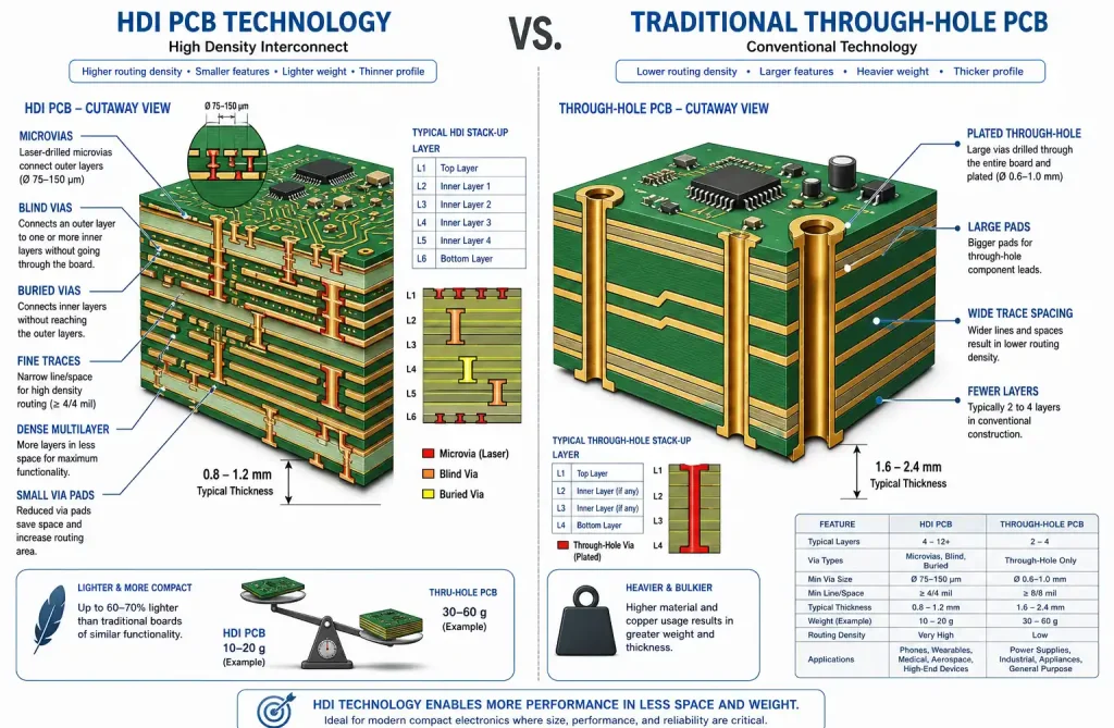
High-Density Interconnect (HDI) technology revolutionizes flight control board design by enabling smaller form factors and reduced layer counts through advanced via structures and fine-line routing capabilities.
Microvia Advantages:
Microvias (typically 0.1-0.15 mm diameter) replace traditional through-hole vias, eliminating unnecessary copper and resin that adds weight. A typical 6-layer HDI board with microvias weighs 20-30% less than an equivalent 8-layer traditional design while offering superior electrical performance.
Blind and buried vias enable more efficient layer utilization, allowing designers to route complex circuits in fewer layers. This directly reduces board thickness and weight while improving signal integrity through shorter interconnect paths.
Any-Layer HDI:
Advanced any-layer HDI constructions allow via connections between any layer pair, maximizing routing density and minimizing layer count. While manufacturing costs increase, the weight savings and performance benefits justify the investment for high-performance drone applications.
Stacked microvias provide vertical interconnect density that traditional designs cannot match, enabling component placement on both board sides with minimal routing congestion. This capability proves essential for integrating multiple sensors and communication modules in compact flight controllers.
Component Selection and Integration Strategies
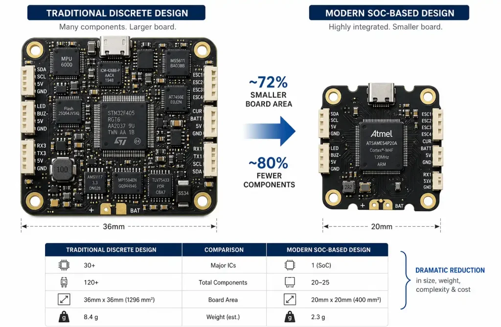
Component selection profoundly impacts both board weight and overall system mass. Modern semiconductor integration enables functionality consolidation that reduces component count, board area, and weight.
System-on-Chip (SoC) Integration:
Contemporary flight control designs increasingly adopt SoCs that integrate processor cores, sensor interfaces, communication peripherals, and power management into single packages. This integration eliminates dozens of discrete components, reducing board area by 40-60% compared to discrete implementations.
Modern flight control SoCs like STM32H7 series or ESP32-S3 integrate ARM Cortex processors with floating-point units, multiple communication interfaces (SPI, I2C, UART, CAN), ADCs, and PWM controllers. This consolidation eliminates external interface chips, reducing component count and board complexity.
Miniaturized Package Technologies:
Wafer-level chip-scale packages (WLCSP) and flip-chip ball grid arrays (FCBGA) offer the smallest footprints for given functionality. A WLCSP IMU occupies 2.5 x 3.0 mm compared to 5 x 5 mm for equivalent QFN packages, enabling 60% area reduction.
0201 and 01005 passive components replace larger 0402 and 0603 sizes where board space permits fine-pitch assembly. While handling challenges increase, the weight savings prove substantial—a typical flight controller might contain 100-200 passive components, where size reduction yields 2-3 grams of savings.
Integrated Passive Devices:
Embedded resistor and capacitor arrays consolidate multiple discrete components into single packages, reducing board area and assembly complexity. These devices prove particularly effective for pull-up/pull-down resistor networks and decoupling capacitor arrays.
Layer Stack-Up Optimization
Strategic layer stack-up design balances electrical performance requirements against weight constraints. Every layer adds copper, prepreg, and core material that increases board mass.
Minimum Viable Layer Count:
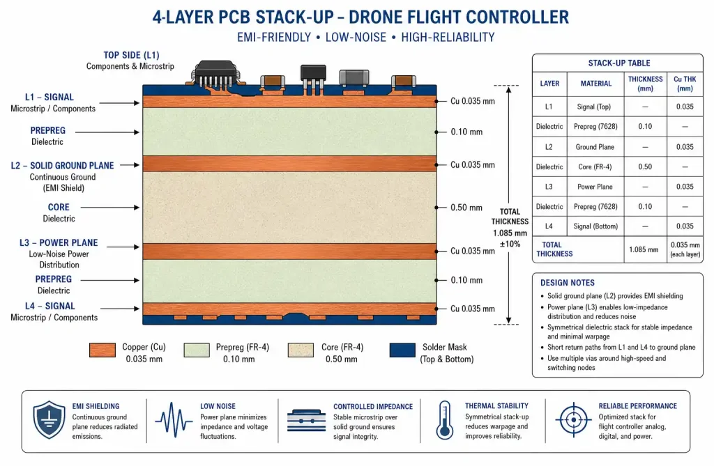
Systematic analysis of routing density, power distribution requirements, and signal integrity constraints determines the minimum layer count. Advanced routing techniques and HDI technology often enable 4-layer designs where traditional approaches require 6-8 layers.
A typical lightweight flight controller stack-up might use: Layer 1 (signal/component), Layer 2 (ground plane), Layer 3 (power plane), Layer 4 (signal/component). This configuration provides solid reference planes for impedance control while minimizing total thickness.
Thin Core and Prepreg Selection:
Using thinner core and prepreg materials reduces overall board thickness and weight. Modern PCB materials support core thicknesses down to 0.1 mm (4 mil) while maintaining mechanical stability. A 4-layer board using thin materials might achieve 0.6 mm total thickness compared to 1.6 mm for standard constructions, reducing weight by 60%.
Careful impedance modeling ensures thin dielectrics maintain required trace impedances for high-speed signals. Narrower traces compensate for reduced dielectric thickness, though this requires tighter manufacturing tolerances.
Advanced Manufacturing Techniques
Modern PCB manufacturing capabilities enable weight optimization strategies previously impractical or cost-prohibitive. Collaboration with manufacturers experienced in aerospace and mobile device production unlocks these advanced techniques.
Laser Direct Imaging (LDI):
LDI technology enables finer trace and space geometries than traditional photolithography, allowing narrower traces that reduce copper usage. Designs can achieve 75 μm (3 mil) traces and spaces compared to 100-125 μm (4-5 mil) for conventional processes, enabling 20-30% copper reduction through more efficient routing.
Sequential Lamination:
Sequential build-up processes create HDI structures with microvias, enabling thinner boards with fewer layers. This technique proves essential for achieving the density required in compact flight controllers while maintaining low weight.
Controlled Depth Milling:
Selective material removal through controlled depth milling creates cavities for component embedding or weight reduction in non-critical areas. Strategic milling can remove 10-15% of board material in areas without circuitry, though this requires careful structural analysis.
Thermal Management in Lightweight Designs
Weight reduction strategies must not compromise thermal performance, as flight controllers generate significant heat from processors, motor drivers, and power management circuits operating in confined spaces.
Thermal Via Arrays:
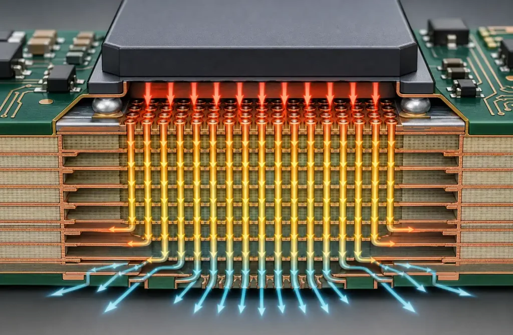
Dense thermal via arrays beneath heat-generating components conduct heat to internal copper planes and opposite board surfaces. A typical thermal via array might contain 20-40 vias of 0.3 mm diameter on 0.6 mm pitch, providing effective thermal paths without adding weight.
Filled thermal vias using thermally conductive epoxy improve heat transfer efficiency by 30-40% compared to unfilled vias, though this adds minimal weight (typically <0.1 gram for a complete board).
Copper Plane Optimization:
Internal copper planes serve dual purposes as electrical references and thermal spreaders. Strategic plane shaping maximizes thermal spreading while minimizing copper mass in areas with low thermal loads.
Passive Cooling Strategies:
Lightweight designs favor passive cooling through optimized airflow paths and thermal spreading rather than heavy heatsinks. Component placement that leverages propeller-induced airflow provides effective cooling without added mass.
Signal Integrity Considerations
Lightweight design strategies must preserve signal integrity for high-speed interfaces connecting processors, sensors, and communication modules. Reduced board thickness and layer counts challenge traditional signal integrity approaches.
Impedance Control in Thin Boards:
Maintaining controlled impedance (typically 50Ω single-ended, 100Ω differential) in thin dielectric stacks requires narrow traces. Precise impedance modeling and manufacturing process control ensure reliable high-speed signal transmission.
Crosstalk Mitigation:
Reduced layer counts and tighter component spacing increase crosstalk risk. Strategic trace routing, guard traces, and ground stitching vias mitigate coupling between sensitive signals. Differential signaling for high-speed interfaces (USB, MIPI, PCIe) provides inherent noise immunity.
Return Path Optimization:
Continuous return paths prove critical for signal integrity in lightweight designs with minimal layer counts. Via stitching along signal path edges and careful plane management ensure low-impedance return paths that minimize EMI and signal degradation.
Power Distribution Network Design
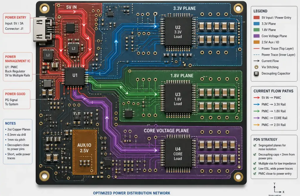
Efficient power distribution networks (PDNs) in lightweight flight controllers must deliver clean power to sensitive analog sensors and digital processors while minimizing copper weight and board area.
Decoupling Strategy:
Strategic decoupling capacitor placement near power pins maintains power integrity while minimizing capacitor count and board area. Modern ceramic capacitors offer high capacitance density in small packages, enabling effective decoupling with minimal weight impact.
Power Plane Segmentation:
Segmented power planes isolate noisy digital supplies from sensitive analog circuits without requiring additional layers. Careful segmentation planning prevents return path discontinuities that degrade signal integrity.
Integrated Power Management:
Modern power management ICs integrate multiple regulators, supervisors, and sequencing logic into compact packages, eliminating discrete components. A single PMIC might replace 5-10 discrete regulators, reducing board area by 30-40% and weight by 1-2 grams.
Testing and Validation Methods
Lightweight flight control boards require rigorous testing to ensure weight reduction strategies don’t compromise reliability or performance in demanding operational environments.
Vibration Testing:
Drone flight controllers experience significant vibration from motors and propellers. Accelerated vibration testing per DO-160 or MIL-STD-810 standards validates mechanical integrity of lightweight constructions. Thin boards may require additional mechanical support or strategic stiffener placement.
Thermal Cycling:
Temperature cycling from -40°C to +85°C (or wider for extreme environment applications) validates solder joint reliability and material compatibility. Lightweight designs using thin substrates and advanced materials require careful validation of thermal expansion matching.
Functional Testing:
Comprehensive functional testing validates all subsystems under realistic operating conditions. Automated test fixtures enable rapid validation of sensor interfaces, communication links, motor control outputs, and power management circuits.
Real-World Case Studies
Case Study 1: Racing Drone Flight Controller
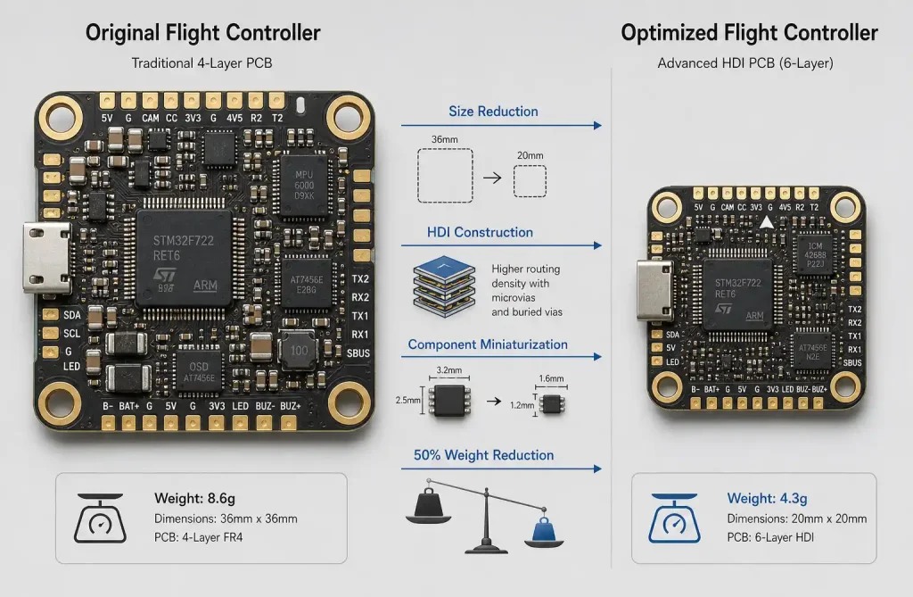
A competitive racing drone manufacturer reduced flight controller weight from 8.5g to 4.2g through systematic optimization. The redesign employed 4-layer HDI construction with 0.5 oz copper on signal layers, Rogers RO4350B substrate, and 0201 passive components. Microvia technology enabled 40% area reduction while improving signal integrity for high-speed IMU interfaces.
Case Study 2: Commercial Delivery Drone
A delivery drone platform achieved 35% weight reduction in its flight control system through SoC integration and advanced packaging. Consolidating discrete processor, sensor interfaces, and communication modules into a custom SoC eliminated 40+ components. WLCSP packaging and embedded passive devices further reduced board area by 50%.
Case Study 3: Long-Endurance Surveillance UAV
A surveillance drone requiring 2+ hour flight times optimized its flight controller for minimum weight and power consumption. The design used 4-layer construction with selective 0.5 oz copper, achieving 5.8g total weight for a full-featured flight controller with integrated telemetry and GPS. Power-optimized component selection extended flight time by 18 minutes.
Future Trends and Emerging Technologies
The evolution of drone flight control board design continues accelerating, driven by advances in materials, manufacturing, and semiconductor integration.
3D Printed Electronics:
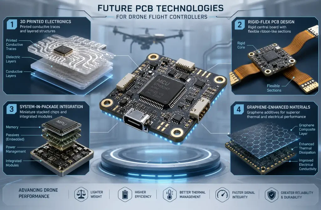
Additive manufacturing of electronic circuits promises revolutionary weight reduction through optimized 3D structures and elimination of traditional substrate materials. While current technology limits resolution and material properties, rapid advancement suggests practical applications within 2-3 years.
Flexible and Rigid-Flex Designs:
Flexible circuit technology enables conformal mounting that optimizes space utilization and reduces connector weight. Rigid-flex constructions combine the benefits of rigid boards for component mounting with flexible interconnects that eliminate connectors and cables.
Advanced Packaging Integration:
System-in-Package (SiP) and Package-on-Package (PoP) technologies integrate multiple die and passive components into single packages, further reducing board area and weight. Future flight controllers may consolidate entire subsystems into advanced packages measuring just 10×10 mm.
AI-Optimized Design Tools:
Machine learning algorithms increasingly optimize PCB layouts for multiple objectives including weight, signal integrity, thermal performance, and manufacturability. These tools explore design spaces beyond human capability, discovering non-obvious optimizations that reduce weight while improving performance.
Graphene and Advanced Materials:
Emerging materials like graphene-enhanced composites promise superior strength-to-weight ratios and thermal properties. While commercial availability remains limited, these materials may enable next-generation lightweight designs with unprecedented performance.
Conclusion
Achieving optimal lightweight design in drone flight control system hardware-software integrated boards requires systematic optimization across materials, manufacturing, components, and architecture. Modern HDI technology, advanced materials, and integrated semiconductors enable weight reductions of 40-60% compared to traditional designs while maintaining or improving performance and reliability.
Successful lightweight design balances multiple competing objectives: weight, cost, performance, reliability, and manufacturability. The strategies outlined in this guide provide a comprehensive framework for developing flight control boards that meet demanding drone application requirements while minimizing weight impact.
As drone applications continue expanding into commercial delivery, infrastructure inspection, precision agriculture, and beyond, lightweight flight control systems will prove increasingly critical to operational viability and competitive advantage. Designers who master these optimization techniques will lead the next generation of UAV innovation.