
PCB Assembly Inspection Standards: IPC-A-610 Classification Explained
When your PCB assembly returns from manufacturing, how do you know if it meets quality standards? IPC-A-610, titled “Acceptability of Electronic Assemblies,” provides the answer. This widely adopted standard defines visual acceptance criteria that determine whether assembled boards pass inspection or require rework.
For engineers specifying PCBA services and quality managers setting acceptance thresholds, understanding IPC-A-610’s three classification levels is essential. The class you select directly impacts manufacturing cost, inspection rigor, and long-term reliability. This guide explains each classification, their differences, and how to choose the right one for your application.
What Is IPC-A-610 and Why It Matters
IPC-A-610 is the electronics industry’s most referenced standard for judging finished, populated circuit boards. Published by IPC (Association Connecting Electronics Industries), it provides illustrated visual criteria for evaluating solder joints, component placement, wire terminations, and overall assembly workmanship.
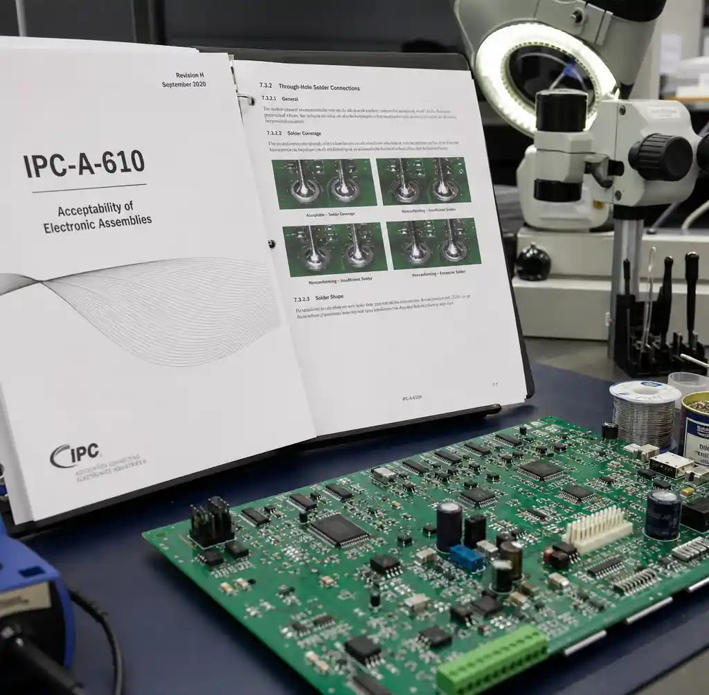
The standard operates entirely on visual inspection principles. Trained inspectors compare actual assembly features against illustrated examples in the standard to determine acceptability. Unlike functional testing that verifies circuit operation, IPC-A-610 focuses on manufacturing quality indicators that predict reliability.
The current edition is IPC-A-610J, released in March 2024. Previous revisions (H, G, F) remain valid for existing programs, though new projects should reference the latest version. The standard coordinates with IPC-J-STD-001 (soldering requirements) to provide comprehensive PCBA quality guidelines.
The Three IPC-A-610 Classifications
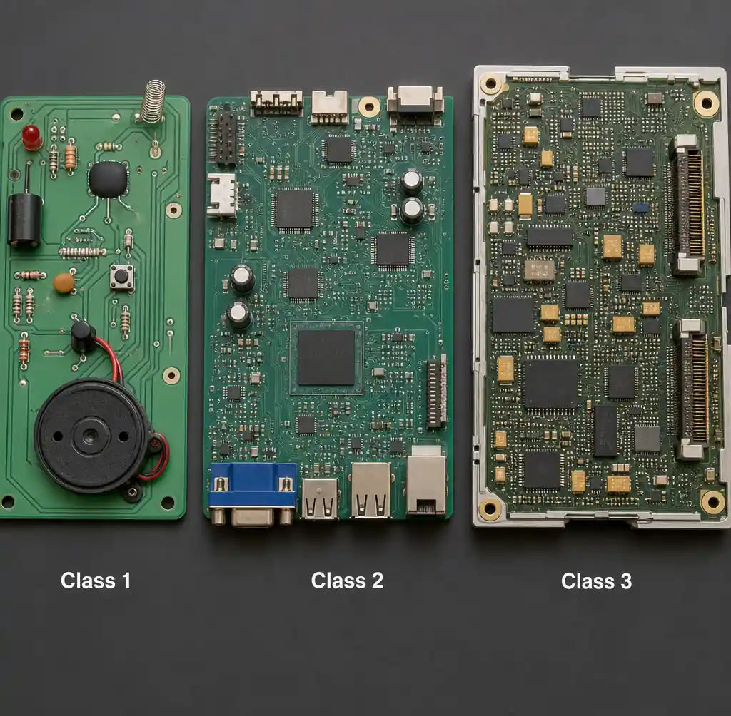
IPC-A-610 defines three performance classes with progressively stricter acceptance criteria. Each class targets different product categories and reliability expectations.
| Classification | Target Application | Acceptance Philosophy | Typical Products |
|---|---|---|---|
| Class 1 | General Electronic Products | Cosmetic appearance matters; occasional imperfections acceptable | Consumer electronics, toys, disposable devices |
| Class 2 | Dedicated Service Electronics | Reliable extended service required; minor visual deviations allowed if functional | Commercial equipment, computers, telecom, industrial controls |
| Class 3 | High Performance/Harsh Environment | Continuous operation critical; zero tolerance for potential failure indicators | Medical devices, aerospace, military, life-safety systems |
Class 1: General Electronic Products
Class 1 applies to products where primary function is important but extended life is not critical. These assemblies serve applications with short service life or where cosmetic appeal outweighs long-term reliability.
Acceptance criteria in Class 1 are the most permissive. Inspectors focus on gross defects that prevent immediate function while accepting minor workmanship variations. Solder joints may show some irregularity, component placement tolerances are wider, and slight contamination is acceptable.
Typical Class 1 use cases: Low-cost consumer electronics, promotional items, single-use diagnostic devices, and products with planned obsolescence cycles under 2 years.
Class 2: Dedicated Service Electronic Products
Class 2 represents the most common classification for commercial and industrial electronics. These products require reliable operation over an extended service life, typically 3-10 years under normal operating conditions.
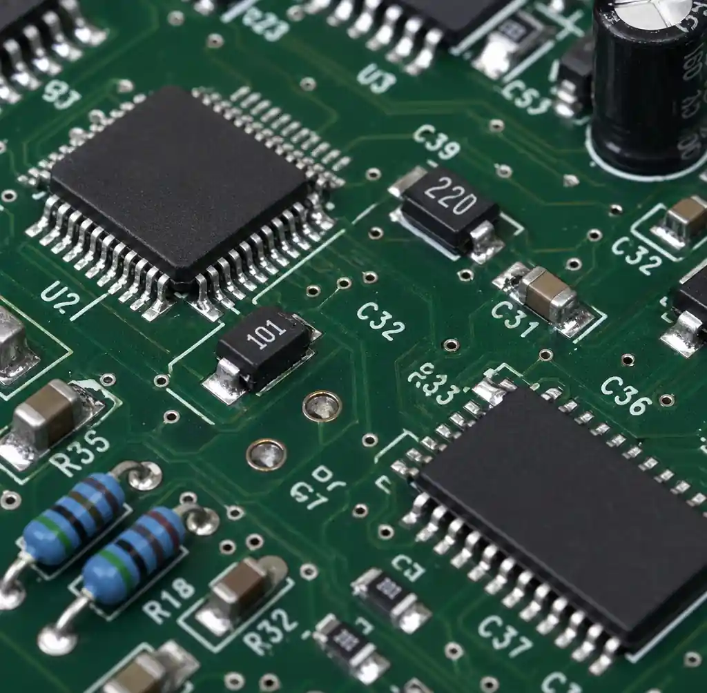
Inspection criteria balance manufacturing cost with reliability. Class 2 allows minor component misalignment if electrical contact remains secure, accepts 50% minimum barrel fill in plated through-holes, and permits small cosmetic irregularities that don’t compromise function. However, any condition indicating poor process control or potential field failure is rejected.
Applications include: Computers and servers, telecommunications equipment, automotive non-safety electronics, industrial automation controllers, and test equipment. Most PCB assembly services default to Class 2 unless otherwise specified.
Class 3: High Performance Electronic Products
Class 3 applies when continuous operation is critical and equipment downtime creates unacceptable risk. These assemblies must demonstrate superior workmanship with zero tolerance for conditions that could lead to field failures.
The inspection criteria are significantly stricter than Class 2. Requirements include 75% minimum barrel fill on through-holes, precise component alignment with minimal offset allowed, complete solder wetting with well-formed fillets, and pristine surface cleanliness. Any visual indicator of marginal process control—even if currently functional—requires rejection.
Critical applications: Non-implantable medical electronics, aerospace avionics, military communications, semiconductor fabrication equipment, industrial safety systems, and life-support machinery. Class 3 adds 15-30% to manufacturing costs due to tighter process control and higher rework rates.
Key Inspection Criteria Across Classifications
Understanding how specific defects are judged across classes clarifies the practical differences between classifications.
Solder Joint Quality
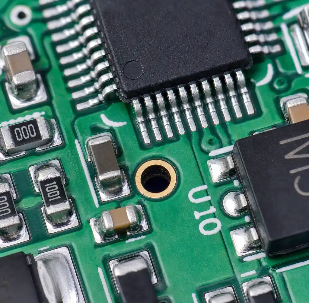
Solder joints receive the most scrutiny in IPC-A-610 inspection. The standard provides detailed photographs showing acceptable and defective joints for each class.
| Solder Joint Feature | Class 1 | Class 2 | Class 3 |
|---|---|---|---|
| Barrel Fill (PTH) | 50% minimum | 75% minimum | 75% minimum |
| Fillet Height | Visible wetting | 1 lead diameter or 2.5mm | 1 lead diameter or 2.5mm |
| Disturbed Joint | Acceptable if electrical contact maintained | Process indicator; rework if severe | Defect; requires rework |
| Insufficient Wetting | Acceptable if >50% coverage | Defect if <75% coverage | Defect if any unwetted area |
| Solder Voids (SMT) | Acceptable if connection maintained | <25% pad area | <25% pad area |
The key difference: Class 1 accepts solder joints that function electrically despite visual imperfections, while Class 3 rejects joints showing any sign of marginal process control even if currently functional.
Component Placement and Alignment
Component positioning criteria vary significantly across classes, particularly for surface mount devices.
Class 1 allows components rotated up to 45° if all terminations contact pads and create electrical connections. End caps on chip resistors may overhang pad edges by 50% as long as one end maintains solder contact.
Class 2 permits maximum 25° rotation and 25% end cap overhang. Components must be centered on pads within tolerance, though minor shifts are acceptable if solder joints appear sound.
Class 3 demands precise alignment with maximum 10° rotation and minimal overhang. Components showing significant positional deviation are rejected even if solder joints test electrically sound, as misalignment indicates process variation that could affect long-term reliability.
Cleanliness and Contamination
Residue requirements tighten considerably across classes, reflecting sensitivity to long-term reliability degradation.
Class 1 accepts visible flux residue and minor contamination that doesn’t interfere with electrical function or conformal coating adhesion. Class 2 requires removal of corrosive flux residues and contamination from high-voltage areas but permits non-corrosive residues. Class 3 mandates thorough cleaning with residue levels below IPC-TM-650 limits, particularly around fine-pitch components where contamination can cause dendritic growth.
Common Defects Identified Under IPC-A-610
Real-world inspection reveals recurring defects that IPC-A-610 addresses systematically.
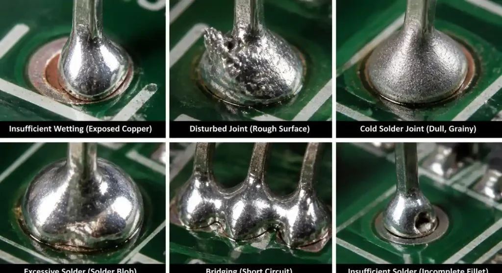
Insufficient solder wetting appears when solder fails to flow properly onto pads or leads, leaving exposed copper. Class 2 and 3 inspectors reject joints with inadequate wetting, while Class 1 may accept them if electrical connection exists.
Disturbed solder joints result from movement during solidification, creating rough, fractured surfaces. These represent process indicators in Class 2—suggesting equipment vibration or thermal issues—and outright defects in Class 3.
Component tombstoning occurs when one end of a chip component lifts off its pad during reflow. All classes reject severe tombstoning, but Class 1 may accept slight lifting if both ends remain partially soldered.
Lifted leads on through-hole components indicate insufficient solder wetting or thermal stress. Class 2 accepts minimal lead lift (<1mm) if the barrel remains filled; Class 3 rejects any visible lead separation from the pad.
Solder bridging between adjacent pins creates short circuits and is rejected in all classes. However, Class 1 may accept very fine bridges on non-critical nets if they clear minimum spacing requirements.
Understanding these common defects helps engineers writing inspection criteria specify appropriate acceptance levels for their application. Your PCB assembly provider should demonstrate capability to identify and correct these issues before shipment.
IPC-A-610 Certification and Training Requirements
The standard only works when inspectors apply it consistently. IPC offers formal certification programs that train and qualify inspection personnel.
CIS Certification (Certified IPC Specialist)
The foundational certification is CIS, a 4-day course covering complete standard application. CIS-certified inspectors learn to correctly identify acceptable conditions, process indicators, and defects across all three classes.
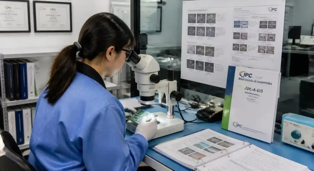
Training includes hands-on inspection of sample assemblies, group exercises comparing student judgments against standard criteria, and written examinations. CIS certification remains valid for 2 years, requiring recertification to stay current with standard updates.
Who needs CIS certification: Quality inspectors, receiving inspection personnel, production line operators performing in-process checks, and supplier quality engineers auditing contract manufacturers.
CIT and CSE Advanced Certifications
CIT (Certified IPC Trainer) qualifications allow individuals to teach IPC-A-610 courses and certify new CIS inspectors. CSE (Certified Standards Expert) represents the highest level, qualifying recipients to interpret standard requirements and serve on IPC committees developing future revisions.
Most manufacturers require CIS certification as minimum qualification for final inspection roles. Larger operations maintain in-house CIT-certified trainers to reduce external training costs and customize instruction to their specific product mix.
Choosing the Right Classification for Your Project
Selecting appropriate IPC class requires balancing reliability requirements against cost constraints. Over-specification wastes resources while under-specification creates field failure risk.
Start with application criticality. If product failure creates safety hazards or unacceptable downtime, Class 3 is appropriate despite higher costs. Medical devices, avionics, and industrial safety controls fall clearly into this category.
Consider service life and environment. Products operating continuously in harsh conditions (temperature extremes, vibration, corrosive atmospheres) benefit from Class 3’s tighter criteria. Consumer electronics with 2-3 year replacement cycles rarely justify beyond Class 2.
Evaluate cost impacts. Class 3 assembly typically costs 15-30% more than Class 2 due to tighter process control, increased inspection time, and higher rework rates. This premium makes sense for low-volume, high-value products but may be prohibitive for cost-sensitive consumer goods.
Review customer expectations. Some industries default to specific classes regardless of technical requirements. Automotive typically specifies Class 2; aerospace defaults to Class 3. Understanding customer norms prevents specification mismatches that delay approval.
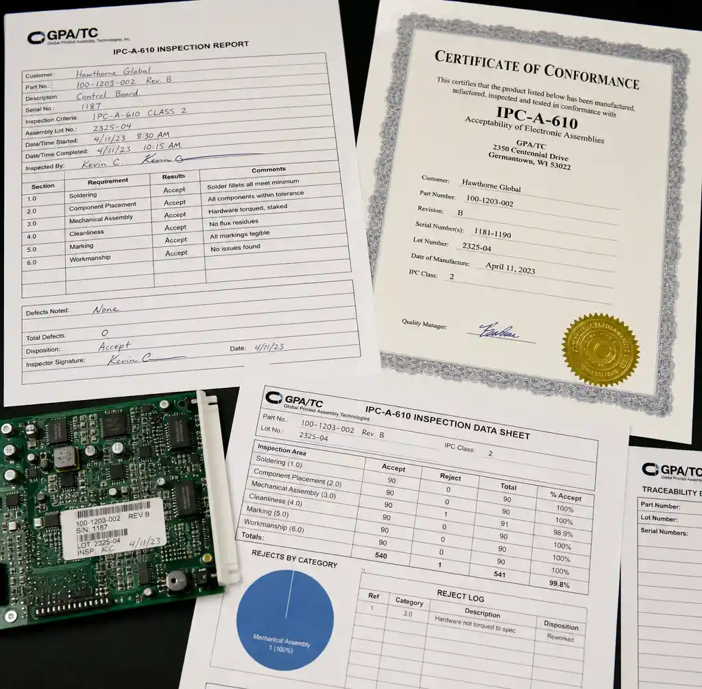
When working with Chinese manufacturers, clearly specify your required class in RFQ documents and purchase orders. Confirm the factory maintains IPC-certified inspectors for your classification level. Request certificates of conformance documenting inspection results against your specified criteria.
IPC-A-610 and Related Standards
IPC-A-610 forms part of an integrated standards ecosystem governing electronics manufacturing.
IPC-J-STD-001: Soldering Requirements
While IPC-A-610 defines acceptance criteria for finished assemblies, IPC-J-STD-001 specifies soldering processes, materials, and procedures. The two standards align closely—J-STD-001 describes how to create joints that meet A-610 acceptance criteria.
Manufacturers typically certify to both standards simultaneously. Assembly operators hold J-STD-001 certification demonstrating proper soldering techniques, while inspectors hold A-610 certification to judge results.
IPC-6012: PCB Qualification and Performance
IPC-6012 establishes bare board acceptance criteria before assembly. Like A-610, it defines three performance classes (1, 2, 3) with corresponding quality requirements.
Matching bare board class to assembly class ensures consistent quality philosophy. A Class 3 assembly on a Class 2 board creates reliability mismatch—the superior assembly workmanship cannot overcome limitations in the substrate.
IPC-A-600: Bare PCB Acceptability
IPC-A-600 provides visual acceptance criteria for bare printed circuit boards before component assembly. It addresses laminate quality, hole plating, copper trace definition, and surface finish. Using consistent classification across bare board (A-600), assembly process (J-STD-001), and finished assembly (A-610) ensures unified quality approach.
Implementing IPC-A-610 in Your Quality System
Adopting IPC-A-610 requires more than purchasing the standard and training inspectors. Effective implementation integrates the criteria into your broader quality management system.
Document your classification selection. Quality plans should explicitly state which IPC-A-610 class applies to each product or product family. Include rationale documenting why that class was selected, referencing application requirements and customer expectations.
Create inspection work instructions. While IPC-A-610 provides acceptance criteria, your procedures must specify inspection frequency, sampling plans, and nonconformance disposition processes. Define how often inspectors examine assemblies, which features receive scrutiny, and who authorizes deviation acceptance.
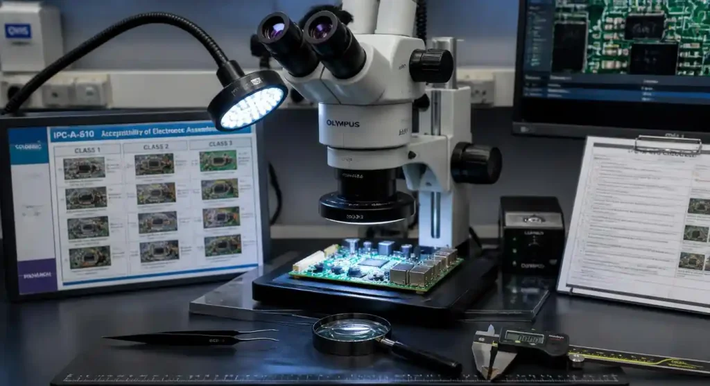
Maintain calibrated inspection equipment. Visual inspection requires proper lighting, magnification, and measurement tools. Low-power stereomicroscopes (10-30x magnification), calibrated calipers, and high-intensity LED lighting are minimum requirements. AOI systems supplement but cannot replace trained human judgment for Class 3 assemblies.
Track defect trends. Record inspection findings systematically to identify recurring issues. If certain defect types appear frequently, root cause investigation and corrective action prevent continued nonconformances. Effective manufacturers review defect pareto charts monthly and drive process improvements accordingly.
Qualify your suppliers. When outsourcing assembly, verify your CM holds current IPC certifications and maintains documented inspection procedures. Request sample inspection reports showing how they record and communicate findings. Include IPC-A-610 compliance requirements in supplier quality agreements.
Frequently Asked Questions
Can a single assembly contain multiple IPC-A-610 classes?
Yes, though this creates complexity. Mixed-class assemblies apply different acceptance criteria to different circuit sections. For example, a medical device might specify Class 3 for life-critical power supply circuitry and Class 2 for non-critical user interface sections. This approach requires clear documentation defining boundaries and training inspectors to apply appropriate criteria per section.
Does IPC-A-610 apply to hand-soldered rework?
Yes. Chapter 7 covers hand soldering and rework operations. Reworked joints must meet the same acceptance criteria as production assemblies. This means Class 3 assemblies require Class 3-level rework quality—a challenging requirement that necessitates skilled technicians and proper equipment.
How does IPC-A-610 handle lead-free soldering?
The standard applies equally to tin-lead and lead-free solder systems. However, lead-free joints exhibit different visual characteristics—they appear duller and grainier than tin-lead joints. Inspectors must understand these appearance differences to avoid incorrectly rejecting acceptable lead-free joints or accepting defective ones.
What happens when customer requirements conflict with IPC-A-610?
IPC-A-610 establishes industry baseline acceptance criteria. Customer specifications may impose stricter requirements, which take precedence. However, customers cannot specify looser criteria and still claim IPC-A-610 conformance. Document any customer-specific requirements clearly and train inspectors on the deviations.
Is automated optical inspection (AOI) sufficient for IPC-A-610 compliance?
AOI systems excel at detecting specific defects like component presence/absence, orientation, and gross solder issues. However, they cannot make nuanced judgment calls about wetting quality, fillet shape, or process indicators that require human assessment. AOI serves as a screening tool, but final Class 2 and especially Class 3 inspection requires trained human inspectors.
How often must inspectors recertify?
IPC certifications (CIS, CIT, CSE) remain valid for 2 years from the issue date. Recertification requires passing updated examinations covering any standard revisions released since the previous certification. Some companies impose shorter recertification cycles (annually) to maintain sharper skills.
Conclusion
IPC-A-610 provides the electronics industry’s most comprehensive visual acceptance criteria for assembled circuit boards. Its three-class structure allows manufacturers to match inspection rigor to application requirements, balancing reliability against cost constraints.
Class 1 serves short-life consumer products where function matters more than longevity. Class 2 addresses the broad commercial and industrial electronics market requiring reliable extended service. Class 3 ensures uncompromising quality for mission-critical applications where field failures create unacceptable consequences.
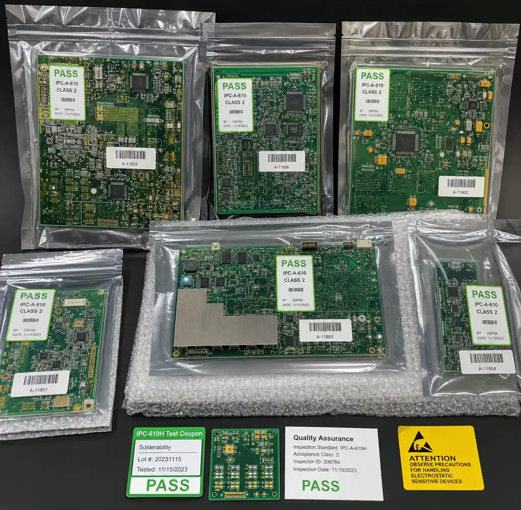
Understanding these classifications and their specific criteria empowers engineers to specify appropriate requirements when sourcing PCB assembly services. Clear communication of your IPC class requirement, coupled with supplier verification of inspection capabilities, prevents costly quality mismatches and ensures delivered assemblies meet your reliability expectations.
Whether prototyping new designs or ramping volume production, partnering with an IPC-certified manufacturer familiar with your target classification streamlines the path from design to reliable product. At Andwin Circuits, our IPC-certified inspection team applies Class 2 and Class 3 criteria daily across diverse applications, from industrial controls to medical devices. Contact us to discuss how our quality systems can support your project requirements.