
PCB Material Properties: Dk, Df, Tg, and CTE Explained for Engineers
Material property mismatches cause 40-60% of signal integrity failures in high-speed PCB designs. Incorrect Dk, Df, Tg, or CTE specifications lead to impedance errors, signal loss, thermal failures, and reliability issues discovered only after production. Hardware engineers designing multilayer boards above 1 GHz or operating beyond 100°C must master these four parameters.
Understanding Critical PCB Material Properties
Four parameters define PCB substrate performance: dielectric constant (Dk) controls signal speed and impedance, dissipation factor (Df) determines loss, glass transition temperature (Tg) sets thermal limits, and coefficient of thermal expansion (CTE) predicts mechanical reliability.
These values appear in laminate datasheets per IPC-4101 and IPC-4103 standards. Standard FR4 suits consumer electronics, while 5G infrastructure and automotive radar require specialty laminates with tight electrical and thermal control.
Dielectric Constant (Dk): Signal Speed and Impedance
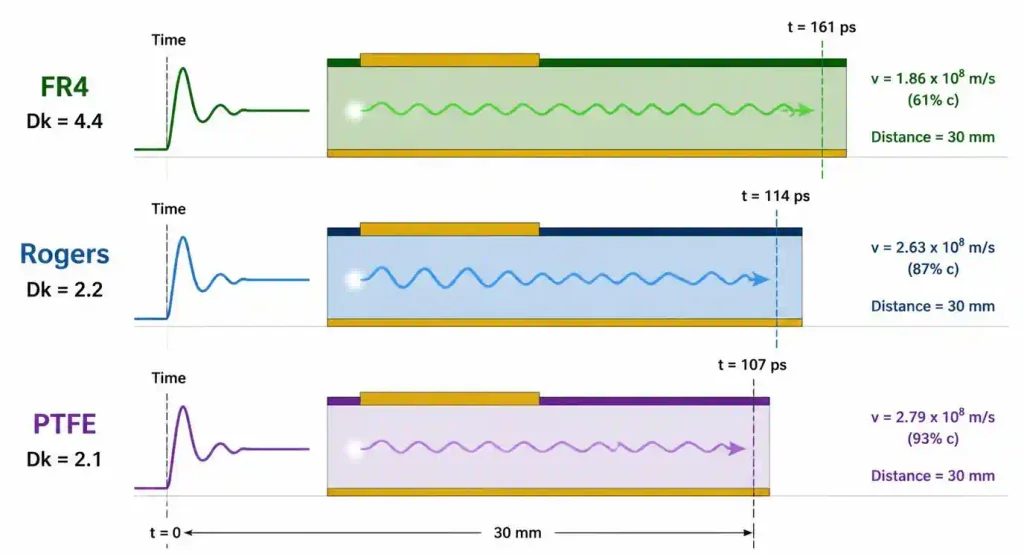
Dielectric constant (relative permittivity, εr) measures how much PCB material slows electromagnetic waves versus vacuum. Standard FR4 shows Dk 4.2-4.5 at 1 MHz, while Rogers PTFE laminates range 2.2-3.5. Lower Dk enables faster propagation for PCIe Gen 5, USB4, and high-speed serial links.
Dk directly controls impedance geometry. A 50-ohm microstrip on FR4 (Dk 4.4) needs 8-10 mil trace width over 1.5 oz copper. Rogers RO4350B (Dk 3.48) requires different dimensions. IPC-2141 defines impedance calculations.
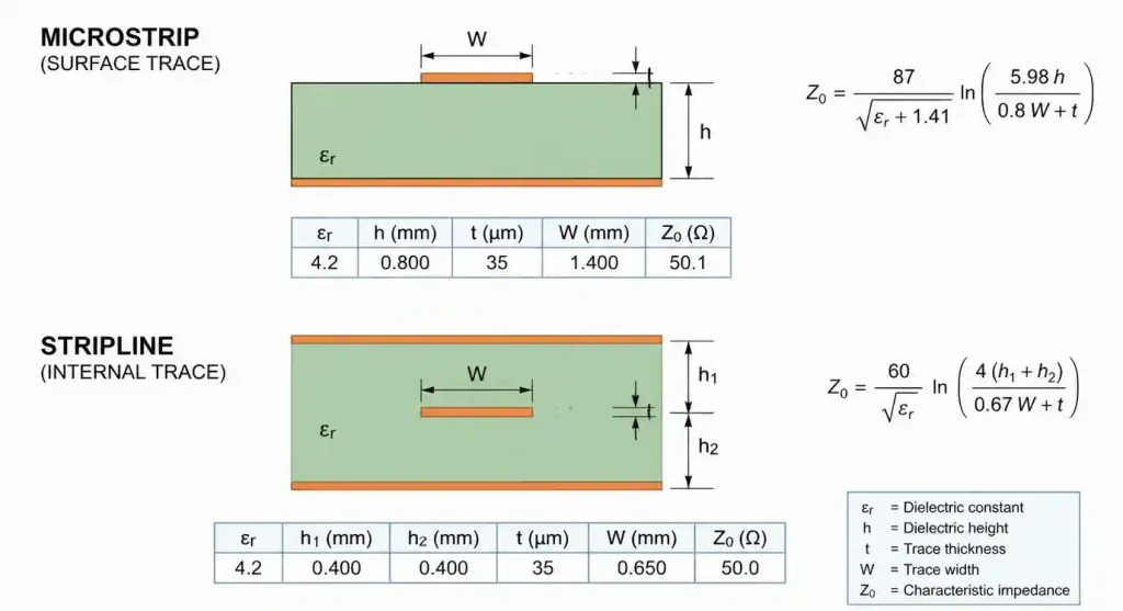
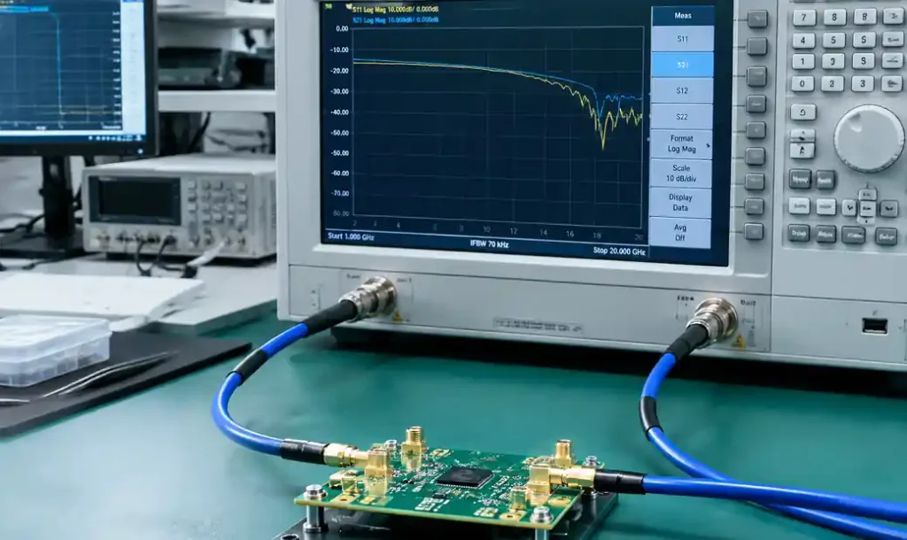
Dk decreases with frequency—FR4 drops 5-8% from 1 MHz to 10 GHz, creating impedance drift. Temperature shifts Dk 2-3% over -40°C to +125°C. Rogers RO4003C maintains ±2% stability to 40 GHz, essential for mmWave 5G and 77-79 GHz automotive radar.
| Material Type | Dk @ 10 GHz | Df @ 10 GHz | Frequency Stability | Temperature Coefficient |
|---|---|---|---|---|
| Standard FR4 | 4.2-4.5 | 0.015-0.020 | ±5-8% to 10 GHz | 50-70 ppm/°C |
| High-Speed FR4 | 3.7-4.2 | 0.008-0.012 | ±3-5% to 10 GHz | 40-60 ppm/°C |
| Rogers RO4350B | 3.48 | 0.0037 | ±2% to 40 GHz | 40 ppm/°C |
| PTFE (RO3003) | 3.00 | 0.0010 | ±1% to 40 GHz | 40-50 ppm/°C |
Dissipation Factor (Df): Signal Loss Control
Dissipation factor (tan δ) quantifies energy converted to heat during signal propagation. Lower Df preserves amplitude and reduces jitter. FR4 (Df 0.020 at 10 GHz) loses 0.5-0.8 dB/inch versus Rogers RO4350B (Df 0.0037) at 0.12 dB/inch—80% reduction.
Below 5 GHz, conductor loss (I²R) dominates. Above 10 GHz, dielectric loss becomes critical. For 56 Gbps PAM4 with 28 GHz Nyquist frequency, Df directly impacts link margin.
PTFE laminates achieve Df below 0.002, essential for 5G MIMO arrays, satellite communications, and automotive radar. Rogers RO3003 (Df 0.0010) provides 20-30 dB improvement over FR4. Specify low-Df materials when traces exceed 6 inches above 10 GHz, but expect 3-5x higher cost versus FR4.
Glass Transition Temperature (Tg): Thermal Stability
Glass transition temperature marks where epoxy transitions from rigid to rubbery state. Below Tg, FR4 maintains 14-17 ppm/°C CTE in XY plane. Above Tg, Z-axis CTE jumps to 250-300 ppm/°C, cracking plated holes and delaminating layers.
Standard FR4 (Tg 130-140°C) suits consumer electronics under 85°C. Lead-free reflow reaches 260°C peak—120°C above Tg. High-Tg materials (170-180°C) survive multiple reflow cycles. IPC-4101 requires Tg measurement per IPC-TM-650 Method 2.4.25. Ensure Tg exceeds maximum operating temperature by 25°C (consumer) or 35°C (automotive/industrial).
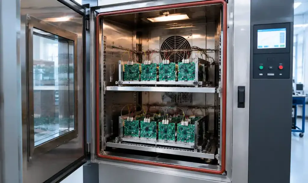
Automotive under-hood applications face -40°C to +150°C with 150-200 annual thermal cycles. Standard FR4 fails in 2-3 years via barrel cracking, while high-Tg laminates (Tg 180°C) achieve 15-year lifespans. Medical devices requiring 134°C sterilization need Tg 170°C minimum. Multilayer PCB designs above 12 layers require high-Tg to prevent lamination warpage.
Coefficient of Thermal Expansion (CTE): Mechanical Reliability
CTE measures dimensional change per degree Celsius (ppm/°C). Copper has 17 ppm/°C CTE, while FR4 shows 14-17 ppm/°C in XY plane but 50-70 ppm/°C in Z-axis. This 3-4x mismatch creates shear stress at plated through-holes during thermal cycling, causing cracks and open circuits.
Each thermal cycle from room temperature to 260°C reflow generates stress proportional to CTE mismatch. After 3-5 reflow cycles, barrel cracks initiate at inner layers. IPC-6012 Class 3 requires Z-axis CTE below 3.5% (25°C to 260°C expansion) for reliability.
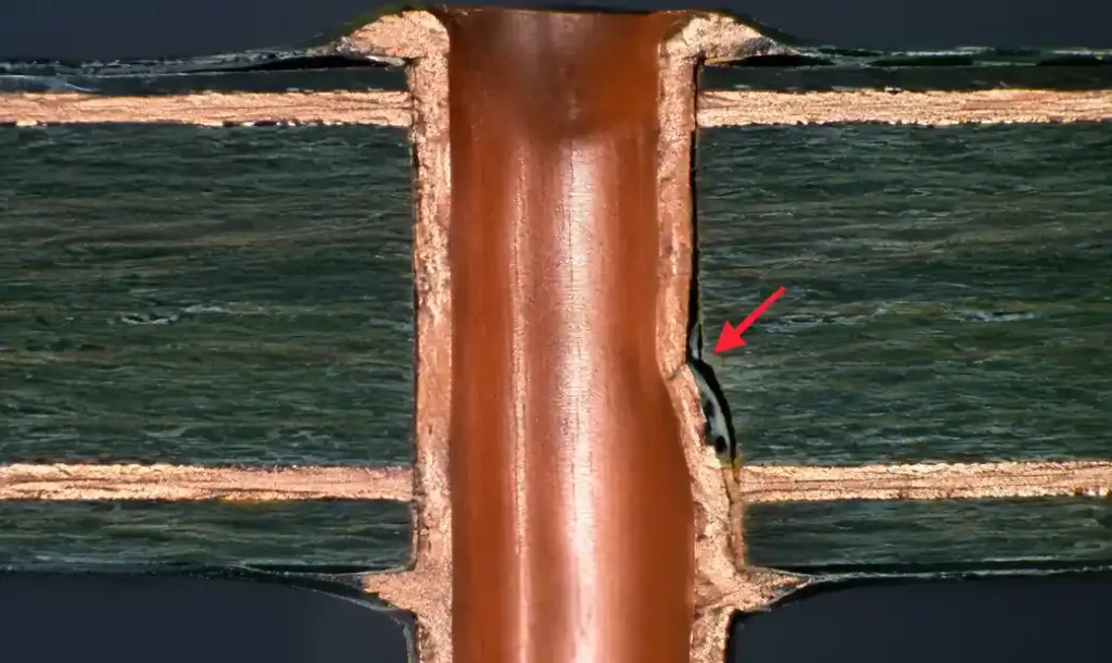
High-Tg laminates achieve lower Z-axis CTE through optimized resin formulation. Standard FR4 expands 3.5-4.5% versus high-performance materials at 2.5-3.0%—a 30-40% reduction improving plated hole reliability in rigid flex PCB and high-layer-count designs. Minimize failures through heavy copper (2-3 oz), back-drilling unused stubs, and proper aspect ratios (thickness-to-diameter ratio below 10:1 standard, 8:1 high reliability).
| Parameter | Standard FR4 | High-Tg FR4 | Rogers RO4350B | PTFE Laminate |
|---|---|---|---|---|
| Tg (°C) | 130-140 | 170-180 | 280 | 260+ |
| XY CTE (ppm/°C) | 14-17 | 12-15 | 10-12 | 24-30 |
| Z CTE (ppm/°C) | 50-70 | 40-50 | 32-46 | 150-240 |
| Z CTE < Tg (%) | 3.5-4.5 | 2.5-3.0 | <3.0 | Variable |
| Max Operating (°C) | 105-110 | 140-150 | 200+ | 200+ |
Material Selection by Application
Consumer Electronics: Standard FR4 (Tg 130-140°C) suits products under 85°C with 1-2 reflow cycles. Digital designs to 5 GHz tolerate Dk variation. Smartphone HDI PCB uses modified FR4 (Dk 4.2, Df 0.012) for WiFi 6E and 5G sub-6 GHz. IoT devices with Bluetooth and WiFi function adequately with FR4 for traces under 3 inches below 6 GHz.
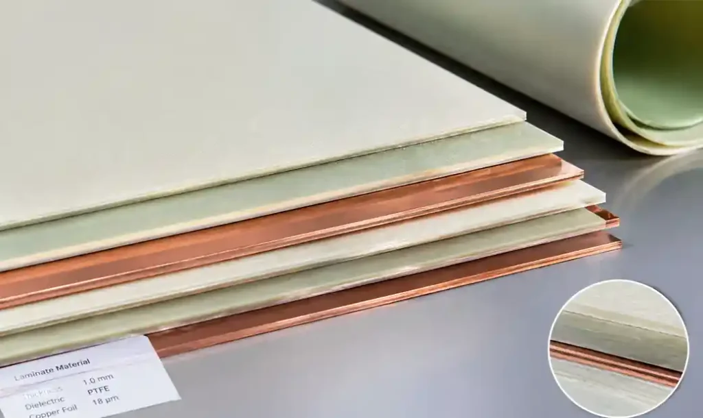
Automotive: IATF 16949-qualified boards must survive -40°C to +150°C over 15 years. Specify high-Tg (Tg 170-180°C minimum), Z-axis CTE below 3.0%, and heavy copper (2-3 oz). ADAS radar at 77-79 GHz requires Rogers RO3003 (Dk 3.0 ±0.04, Df <0.0013) for antenna arrays. Automotive Ethernet needs controlled impedance with temperature-stable Dk.
5G Infrastructure: Massive MIMO base stations use metal core PCB with Rogers or PTFE layers, combining thermal management (3-8 W/mK) with low loss. Power amplifiers need aluminum or copper cores bonded to RO4350B while dissipating 50-100W. Millimeter wave 5G (24-40 GHz) requires PTFE laminates (Dk 2.2-3.0, Df <0.002) to minimize insertion loss across 64-256 element arrays.
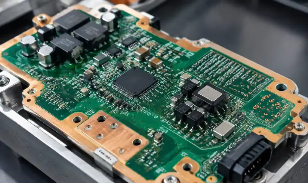
Medical/Aerospace: Medical implantables follow ISO 13485 with high-Tg polyimide flex bonded to FR4 rigid sections. Materials must withstand 134°C steam sterilization for 10-year lifespans. Aerospace specifies IPC-6012 Class 3 with additional Tg, CTE, and moisture absorption requirements. Space applications use polyimide (Tg 250-280°C) for radiation resistance and outgassing control per DO-160 standards.
FAQ
What Dk value should I specify for PCIe Gen 5 or USB4 designs?
PCIe Gen 5 (32 GT/s) and USB4 (40 Gbps) operate at 16 GHz and 20 GHz Nyquist frequencies. Specify Dk 3.7-4.2 at 10 GHz for optimal impedance control. Rogers RO4350B (Dk 3.48) provides excellent performance, while high-speed FR4 (Dk 3.9-4.1, Df <0.010) balances cost and performance for traces under 12 inches. Dk stability across frequency (±2%) matters more than absolute value.
How does moisture affect PCB material properties?
FR4 absorbs 0.1-0.3% moisture at 23°C/50% RH, increasing Dk by 0.1-0.3 units and Df by 15-30%. This shifts impedance 2-3 ohms. IPC-4101 requires baking at 105-120°C for 2-4 hours before lamination to reduce moisture below 0.05%. Moisture causes explosive delamination at 260°C reflow when vapor pressure exceeds 40 atmospheres. Always pre-bake per IPC-J-STD-033.
Can I mix FR4 and Rogers materials in one stackup?
Yes, hybrid stackups use Rogers for RF sections bonded to FR4 for digital layers, reducing cost. However, CTE mismatch (Rogers 10-12 ppm/°C versus FR4 14-17 ppm/°C) creates delamination risk. Use bond enhancer films at material transitions and modified lamination cycles with extended pressure dwell at 175-185°C. Controlled impedance design requires careful analysis since Dk steps affect field distribution.
What is the relationship between Tg and operating temperature?
Maximum continuous operating temperature should not exceed Tg minus 25°C (consumer) or Tg minus 35°C (automotive/industrial). Standard FR4 (Tg 130-140°C) limits operation to 105-110°C, inadequate for automotive under-hood (150°C) or medical sterilization (134°C). High-Tg materials (170-180°C) enable 135-145°C operation. Self-heating adds 10-30°C junction rise above ambient, requiring derating.
How do I reduce signal loss in high-frequency designs?
Below 5 GHz, use heavier copper (1-2 oz) and wider traces to reduce conductor loss. Above 10 GHz, specify low-Df materials like Rogers RO4350B (Df 0.0037) or RO3003 (Df 0.0010). Smooth copper foil reduces conductor loss 20-30% versus standard electrodeposited copper above 10 GHz. For critical RF paths, use HDI PCB with laser-drilled microvias to minimize via stub reflections.
What material specifications matter for automotive PCBs?
Automotive electronics require high-Tg (Tg 170-180°C minimum), Z-axis CTE below 3.0%, heavy copper (2-3 oz), and AEC-Q200 qualification with 1000-2000 thermal cycles from -40°C to +150°C. IATF 16949 certification ensures process control. Power electronics use metal core PCB with 3-8 W/mK thermal conductivity. ADAS radar demands Rogers laminates with Dk stability ±2% across temperature for 77 GHz arrays.
Conclusion
PCB material properties—Dk, Df, Tg, and CTE—determine electrical performance, thermal stability, and mechanical reliability. Dielectric constant controls signal speed and impedance, dissipation factor determines loss, glass transition temperature sets thermal limits, and thermal expansion predicts mechanical failures. Standard FR4 suits consumer electronics below 5 GHz and 85°C, while high-speed digital, RF, automotive, and medical applications require specialty materials with controlled electrical and thermal specifications per IPC-4101.
Material selection balances performance, reliability, and cost based on operating frequency, temperature range, thermal cycling, and quality requirements. Specify Dk and Df at operating frequency, ensure Tg exceeds maximum temperature by 25-35°C, and control Z-axis CTE below 3.5% for Class 3 reliability. Design practices like controlled impedance, heavy copper, and proper via aspect ratios maximize reliability.
Andwin Circuits offers high-quality multilayer PCB manufacturing with advanced material selection up to 50 layers and specialty laminates including Rogers, PTFE, and high-Tg FR4. Our ISO 9001 and IATF 16949 certified production delivers fast 7-day turnaround with engineering support for material selection, stackup design, and signal integrity analysis. Contact us for custom PCB solutions and factory-direct pricing.