
PCB Material Selection Guide: FR4, Rogers, Polyimide, and Ceramic
If you want to select the right PCB substrate material for reliable performance and cost-effective manufacturing, then you will need to understand the critical differences between FR4, Rogers, polyimide, and ceramic materials in terms of electrical properties, thermal performance, and application requirements.
Material selection accounts for 35-50% of total PCB performance in high-frequency and thermal-critical applications. Wrong material choices lead to signal integrity failures, thermal management issues, and costly redesigns. This guide compares the four essential PCB substrate materials across critical parameters to help you make informed decisions.
PCB Substrate Materials Overview
PCB substrate material is the base insulating layer that provides mechanical support, electrical isolation, and thermal management for electronic components. The substrate determines electrical performance, maximum operating temperature, flexibility, and manufacturing compatibility.
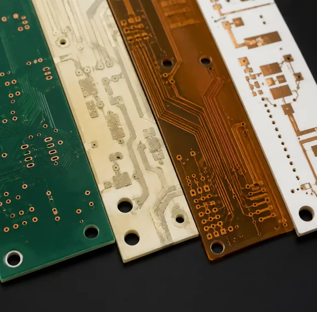
Four primary substrate categories serve different engineering requirements. FR4 epoxy-glass composite provides cost-effective performance for general electronics below 1 GHz. Rogers high-frequency laminates use ceramic-filled PTFE or hydrocarbon materials for RF and microwave circuits. Polyimide materials enable flexible circuits withstanding extreme temperatures. Ceramic substrates deliver exceptional thermal conductivity for high-power applications.
You should base material selection on operating frequency, power dissipation, temperature range, flexibility needs, and cost constraints. FR4 serves most consumer electronics. Telecommunications equipment requires Rogers materials. Wearable devices use polyimide flex circuits. High-power LEDs and RF amplifiers benefit from ceramic substrates.
FR4 Material Properties
FR4 is a composite material made from woven fiberglass cloth impregnated with flame-retardant epoxy resin. This industry-standard substrate accounts for 70-80% of all PCB manufacturing due to balanced properties and low cost.
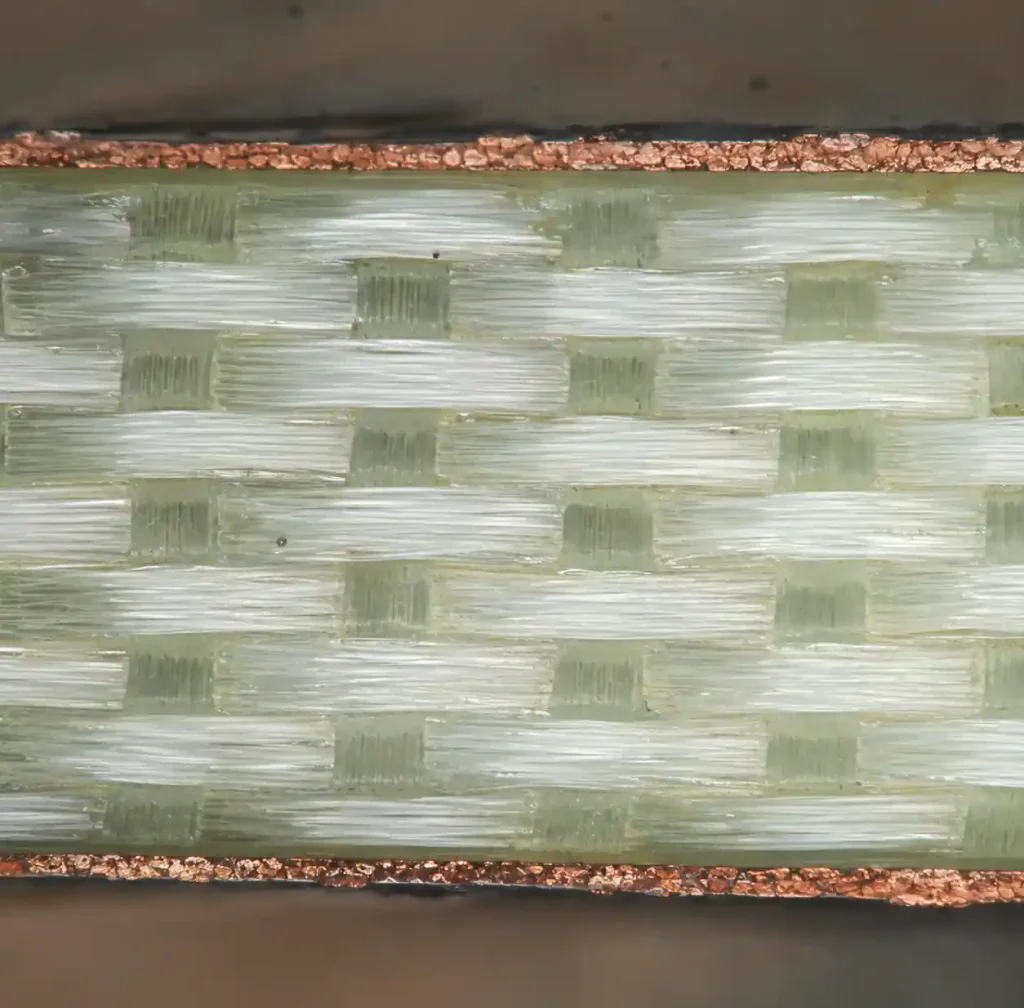
The designation “FR4” refers to Flame Retardant grade 4, meeting UL 94V-0 standards. Standard FR4 exhibits dielectric constant (Dk) of 4.2-4.8 at 1 MHz and dissipation factor (Df) of 0.015-0.025, suitable for digital circuits and low-frequency applications.
You can specify different FR4 grades based on glass transition temperature (Tg). Standard FR4 has Tg of 130-140°C for consumer electronics. High-Tg FR4 (170-180°C) serves automotive and industrial applications. Lead-free assembly requires high-Tg materials withstanding multiple reflow cycles at 260°C without delamination.
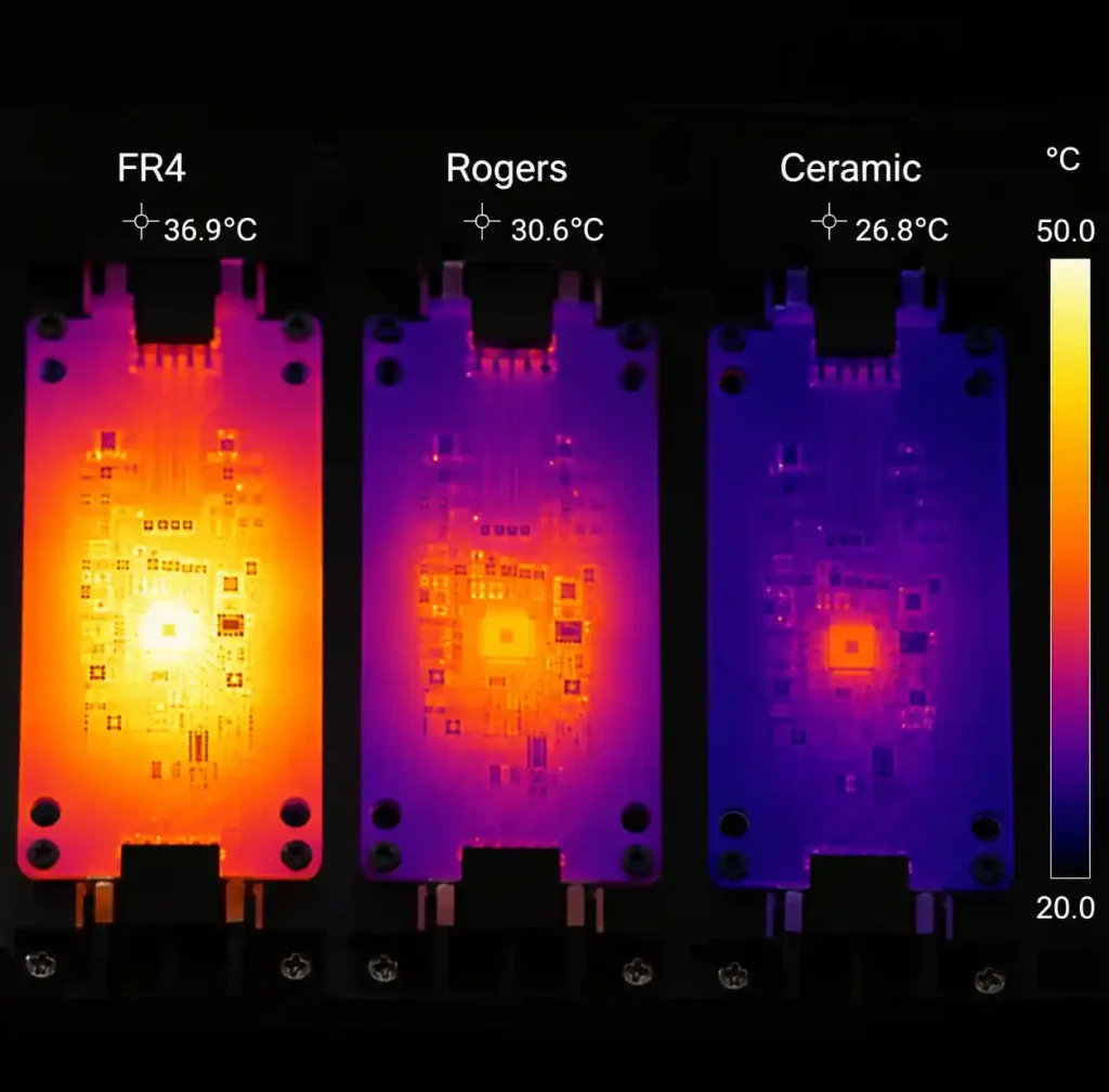
FR4 thermal conductivity of 0.3-0.4 W/mK limits heat dissipation compared to specialized thermal substrates. For thermal management requiring superior heat extraction, consider metal core or ceramic alternatives. FR4 works well where component power dissipation remains below 1-2W per device.
Rogers High-Frequency Materials
Rogers Corporation manufactures advanced circuit materials for high-frequency RF and microwave applications where FR4 performance is insufficient. These materials use ceramic-filled PTFE or hydrocarbon compositions providing stable electrical properties across temperature and frequency ranges.
| Rogers Series | Dielectric Constant | Loss Tangent | Applications |
|---|---|---|---|
| RO4003C | 3.38 ±0.05 | 0.0027 | Cellular base stations, automotive radar |
| RO4350B | 3.48 ±0.05 | 0.0037 | High-speed digital, RF amplifiers |
| RO5880 | 2.20 ±0.02 | 0.0009 | Aerospace, satellite, mmWave 5G |
Rogers materials deliver three critical advantages over FR4 for high-frequency designs. First, tight dielectric constant tolerance (±2% vs FR4’s ±10%) enables precise impedance control. Second, low loss tangent (0.001-0.004 vs FR4’s 0.015-0.025) minimizes signal attenuation at GHz frequencies. Third, stable electrical properties maintain performance across -55°C to +125°C.
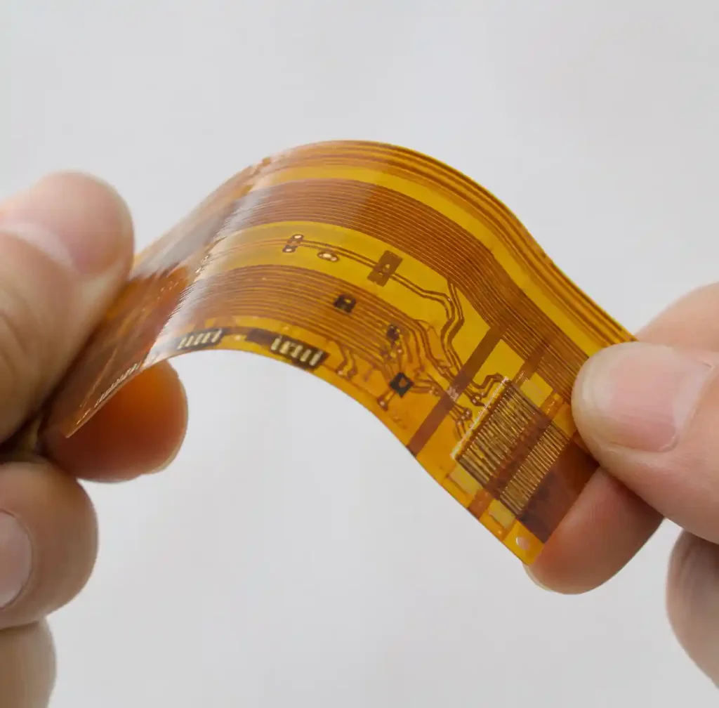
You should specify Rogers materials for applications above 1 GHz where signal integrity is critical. RO4000 series provides best cost-performance for 5G and automotive radar at 24-77 GHz. PTFE-based RO5000 series serves aerospace applications requiring ultra-low loss above 30 GHz.
Manufacturing Rogers PCBs requires modified processing compared to standard FR4. You can use hybrid stackups combining Rogers high-frequency layers with FR4 structural layers to optimize both performance and cost.
Polyimide Flexible Materials
Polyimide is a high-performance polymer providing exceptional thermal resistance, chemical stability, and mechanical flexibility for flexible and rigid-flex circuit applications. This material maintains properties at continuous operating temperatures up to 200°C, far exceeding FR4 capabilities.
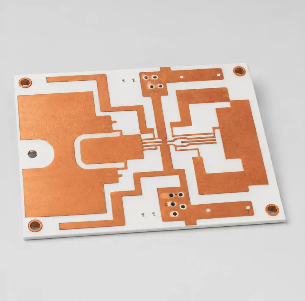
Polyimide substrates use aromatic polymer chains creating glass transition temperature above 300°C. The most common polyimide film is DuPont Kapton, available in thicknesses from 12.5μm to 125μm. Thinner films enable tighter bend radius, while thicker films provide improved dimensional stability.
Electrical properties include dielectric constant of 3.4-3.5 at 1 MHz and dissipation factor of 0.002-0.003. These characteristics allow polyimide flex circuits to operate at frequencies up to several GHz, suitable for IoT and wireless devices. Low moisture absorption (<0.5%) maintains stable performance in humid environments.
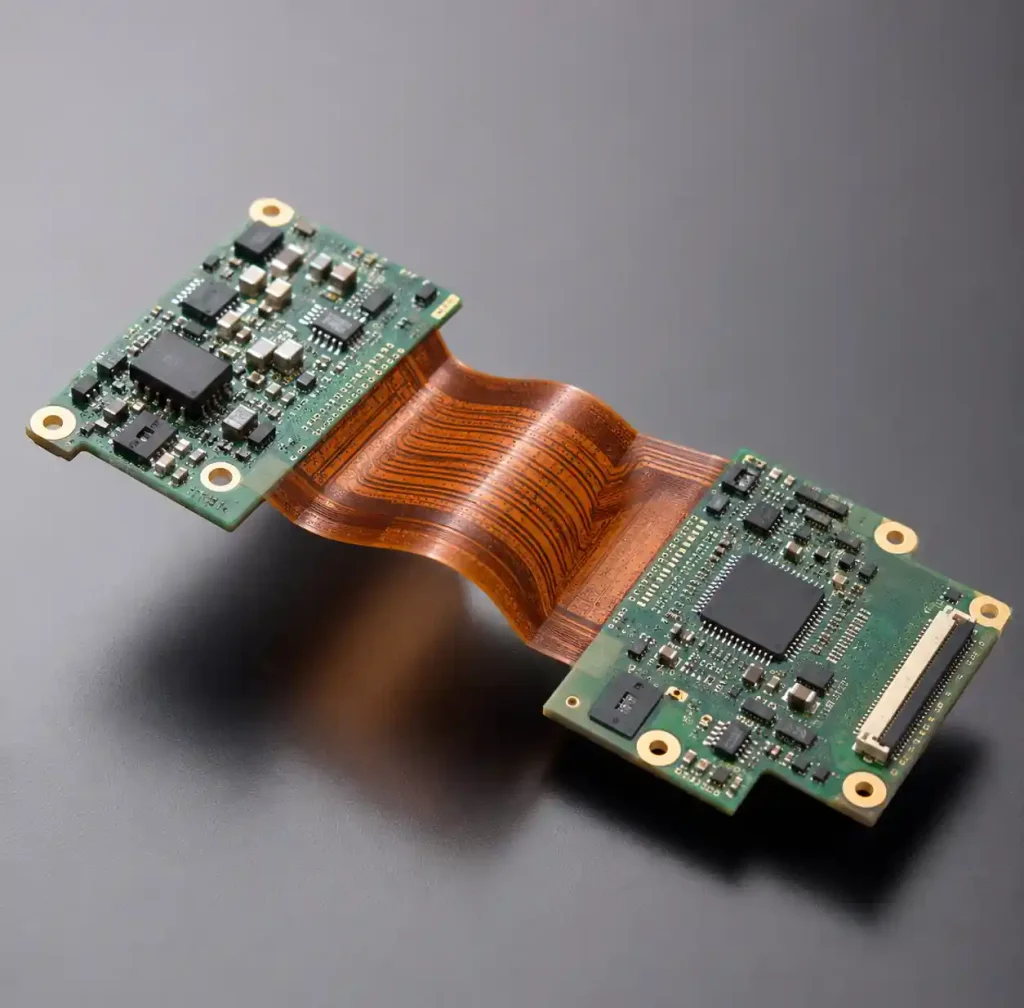
You can specify polyimide materials for three distinct categories. Dynamic flex circuits require repeated bending using rolled-annealed copper. Flex-to-install applications involve one-time bending during assembly. Rigid flex PCB combines polyimide flex sections with FR4 rigid areas, eliminating connectors and improving reliability.
Ceramic Substrate Materials
Ceramic PCB substrates use alumina (Al₂O₃) or aluminum nitride (AlN) as base material, providing exceptional thermal conductivity and high-temperature performance unmatched by organic materials. These substrates serve high-power electronics requiring superior heat dissipation in compact form factors.
Alumina ceramic (96% or 99.6% purity) delivers thermal conductivity of 24-28 W/mK, approximately 80 times higher than FR4. Aluminum nitride achieves 150-170 W/mK thermal conductivity, approaching copper while maintaining excellent electrical insulation. This performance enables direct mounting of high-power semiconductors without intermediate thermal interface materials.
| Property | Alumina (96%) | Aluminum Nitride | FR4 |
|---|---|---|---|
| Thermal Conductivity | 24-28 W/mK | 150-170 W/mK | 0.3-0.4 W/mK |
| Max Operating Temp | 350°C+ | 350°C+ | 130-180°C |
| CTE | 6.5-7.2 ppm/°C | 4.5-5.7 ppm/°C | 14-17 ppm/°C |
Ceramic substrates use specialized metallization processes including Direct Bond Copper (DBC) or Active Metal Brazing (AMB). DBC process bonds copper foil directly to ceramic through high-temperature oxidation, creating copper layers of 0.2-0.6mm thickness.
You should specify ceramic PCB when thermal requirements exceed metal core capabilities or when operating temperatures exceed 150°C. High-power RF amplifiers dissipating 50-200W benefit from ceramic’s combination of thermal conductivity and low dielectric loss. The coefficient of thermal expansion of aluminum nitride (4.5-5.7 ppm/°C) closely matches silicon semiconductors (2.6 ppm/°C), reducing thermal stress during temperature cycling.
Material Comparison
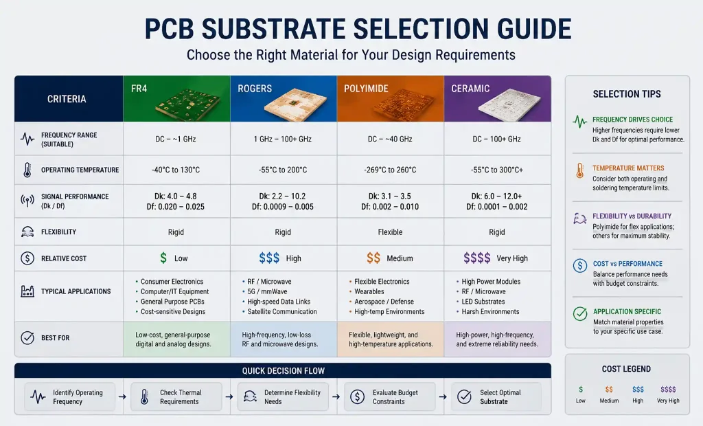
Understanding performance differences across key parameters helps you select the optimal substrate material for your application requirements.
| Parameter | FR4 | Rogers | Polyimide | Ceramic (AlN) |
|---|---|---|---|---|
| Dielectric Constant | 4.2-4.8 | 3.38-3.48 | 3.4-3.5 | 8.8 |
| Loss Tangent | 0.015-0.025 | 0.0027-0.0037 | 0.002-0.003 | 0.0001 |
| Thermal Conductivity | 0.3-0.4 W/mK | 0.6-0.7 W/mK | 0.12-0.2 W/mK | 150-170 W/mK |
| Max Temperature | 130-180°C | 280°C | 200-300°C | 350°C+ |
| Flexibility | Rigid | Rigid | Flexible | Rigid |
| Cost (Relative) | 1× | 3-5× | 2-4× | 10-20× |
Electrical Performance
FR4 dielectric constant varies ±10% across manufacturing lots and changes with frequency and temperature. This variation creates impedance tolerance of ±15-20% without careful stackup control. For high-speed digital circuits above 1 Gbps, you must account for this variability. High loss tangent limits usable frequency range to approximately 1-2 GHz.
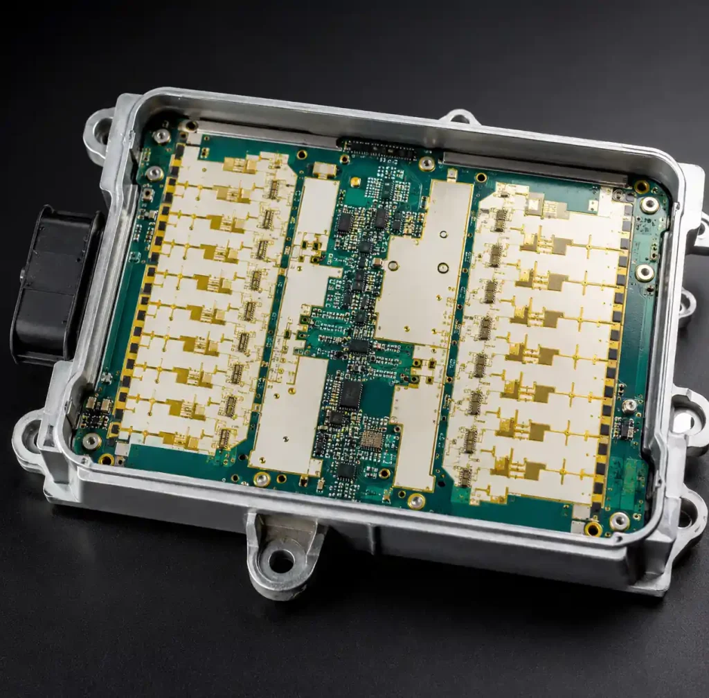
Rogers materials maintain dielectric constant within ±2% tolerance and exhibit minimal frequency dependence up to 40 GHz. This stability enables precise 50-ohm and 100-ohm transmission line design for RF circuits and millimeter-wave applications. Loss tangent 5-10 times lower than FR4 preserves signal amplitude.
Polyimide provides stable dielectric properties with low moisture absorption, critical for flex circuits exposed to varying environmental conditions. Ceramic substrates offer extremely low loss tangent ideal for RF power amplifiers, though higher dielectric constant (8-9 vs 3-4) requires wider traces.
Thermal Performance
FR4’s low thermal conductivity (0.3-0.4 W/mK) requires thermal management through copper pours, thermal vias, and external heat sinks. For components dissipating more than 2-3W, you should implement thermal vias connecting pads to copper planes.
Rogers materials provide slightly improved thermal conductivity (0.6-0.7 W/mK) but thermal performance is not their primary advantage. For high-power RF applications, combine Rogers circuit layers with metal core bases.
Polyimide’s thermal conductivity (0.12-0.2 W/mK) is lower than FR4, making thermal management challenging. However, continuous operating temperature of 200°C and peak resistance to 300°C enable survival in extreme environments.
Ceramic substrates deliver thermal conductivity 500-600 times higher than FR4, enabling direct die attach. This performance allows high-power components to operate at lower junction temperatures, improving reliability and efficiency.
Cost Analysis
FR4 provides the most economical solution at $5-15 per square foot for standard grades. The material processes with standard equipment and maintains short lead times of 5-10 days.
Rogers materials cost 3-5 times more than FR4, with typical pricing of $40-100 per square foot. RO4000 series offers best cost-performance ratio for commercial applications. Lead times extend to 10-15 days.
Polyimide flexible circuits cost 2-4 times standard FR4 pricing due to specialized coverlay materials and precise registration requirements. You should evaluate total system cost including connector elimination when comparing flex versus rigid solutions.
Ceramic substrates represent highest cost at 10-20 times FR4 pricing ($150-400 per board). However, superior thermal performance can eliminate external heat sinks, potentially offsetting substrate cost through system-level savings.
Application-Based Selection
Different applications have distinct electrical, thermal, mechanical, and environmental requirements favoring specific substrate materials.
Consumer Electronics and IoT
Standard consumer products including smartphones, tablets, and IoT devices use FR4 for cost-effective manufacturing. High-Tg FR4 supports lead-free assembly and provides adequate performance for digital circuits below 1 GHz. Specify polyimide flex circuits for battery connections, display interfaces, and hinges. For RF sections (WiFi, Bluetooth, cellular), consider Rogers materials or hybrid stackups.
Telecommunications and 5G
Telecommunications equipment operating at GHz frequencies requires Rogers materials for RF front-ends, power amplifiers, and antenna arrays. 5G frequency range (sub-6 GHz and mmWave 24-40 GHz) demands tight dielectric constant tolerance and low loss tangent. RO4350B serves sub-6 GHz applications cost-effectively, while RO5880 handles mmWave frequencies. Ceramic substrates support high-power RF amplifiers in base stations.
Automotive Electronics
Automotive applications require materials withstanding wide temperature ranges (-40°C to +125°C), thermal cycling, and harsh environments. High-Tg FR4 serves most electronic control units, infotainment systems, and sensor modules. Rogers materials support automotive radar (24 GHz, 77-81 GHz) and V2X communication. Polyimide flex circuits enable reliable interconnections in door modules and dashboard assemblies. Ceramic substrates serve electric vehicle power electronics and LED headlights.
Medical Devices
Medical device PCBs require reliability and compliance with IPC-6012 Class 3 standards. FR4 provides adequate performance for most diagnostic equipment and patient monitors. Polyimide flex circuits enable compact wearable medical sensors and implantable device interconnects. Specify polyimide materials meeting USP Class VI biocompatibility when PCB components contact bodily fluids.
Industrial and Power Electronics
Industrial control systems and power electronics prioritize long-term reliability under continuous operation. High-Tg FR4 with heavy copper serves motor drives, PLCs, and power supplies below 5 kW. Metal core PCBs provide cost-effective thermal management for power converters. Ceramic substrates enable high-power density designs for traction inverters and renewable energy systems requiring 10-100 kW power handling.
FAQs
What is the difference between FR4 and Rogers PCB materials?
FR4 uses fiberglass and epoxy resin with dielectric constant of 4.2-4.8 and loss tangent of 0.015-0.025, suitable for digital circuits below 1 GHz. Rogers materials use ceramic-filled PTFE or hydrocarbon with tightly controlled dielectric constant (±2%) and loss tangent 5-10 times lower than FR4, enabling high-frequency RF applications. Rogers costs 3-5 times more but provides superior signal integrity above 1 GHz where FR4 signal loss becomes excessive.
When should I use polyimide instead of FR4?
Specify polyimide when your design requires flexibility (dynamic flexing or flex-to-install), continuous operating temperatures above 150°C, or exposure to harsh chemicals. Polyimide enables compact product designs by eliminating connectors, reduces assembly weight, and survives extreme environments. Use FR4 for cost-sensitive rigid applications operating below 130°C, as FR4 costs 50-75% less than polyimide flex circuits.
What applications require ceramic PCB substrates?
Ceramic substrates are specified when thermal requirements exceed metal core PCB capabilities, typically for components dissipating 10W+ per device in compact packages. High-power RF amplifiers (50-200W), high-brightness LED arrays, electric vehicle power modules, and laser diode drivers benefit from ceramic’s 150-170 W/mK thermal conductivity. The 10-20× cost premium is justified when thermal performance directly enables the application or eliminates expensive external cooling systems.
Can I mix different materials in one PCB stackup?
Yes, hybrid stackups combine different materials to optimize cost and performance. Common configurations include Rogers high-frequency layers for RF sections with FR4 structural layers for digital circuitry, reducing material costs 40-60% versus all-Rogers construction. Rigid flex PCB designs combine FR4 rigid sections for component mounting with polyimide flex sections for interconnection. Work with your PCB manufacturer to verify material compatibility and thermal expansion matching for hybrid constructions.
How does material selection affect PCB manufacturing lead time?
Standard FR4 delivers fastest turnaround with 5-10 day lead times due to widespread availability and standard processing. Rogers materials require 10-15 days as fewer manufacturers offer high-frequency capabilities. Polyimide flex circuits need 12-20 days for coverlay lamination and forming. Ceramic substrates require 3-6 weeks for DBC metallization. For quick turn assembly projects under tight deadlines, material availability becomes a critical selection factor.
What is the frequency limit for FR4 material?
FR4 performs adequately up to approximately 1-2 GHz depending on trace length, stackup design, and signal loss budget. Above 2 GHz, FR4’s high loss tangent (0.015-0.025) causes significant signal attenuation, and dielectric constant variation degrades impedance control. For frequencies of 2-10 GHz, consider RO4000 series Rogers materials. Above 10 GHz and for millimeter-wave applications (24-40 GHz), specify low-loss PTFE-based materials like RO5880.
Conclusion
FR4, Rogers, polyimide, and ceramic materials serve distinct requirements in PCB design. FR4 provides cost-effective performance for digital circuits below 1 GHz at baseline cost. Rogers laminates deliver precise dielectric properties essential for RF and microwave applications at 3-5× FR4 cost. Polyimide enables flexible circuits withstanding extreme temperatures at 2-4× FR4 cost. Ceramic substrates offer exceptional thermal conductivity (150-170 W/mK) for high-power applications at 10-20× premium.
Select FR4 for cost-sensitive applications with standard performance requirements. Choose Rogers when frequency exceeds 1 GHz or tight impedance control is critical. Specify polyimide for flexibility or high-temperature operation. Use ceramic when thermal dissipation requirements exceed metal core PCB capabilities or operating temperatures surpass 150°C.
If you need high-quality PCB manufacturing with expert material selection support, Andwin Circuits offers advanced capabilities up to 50 layers with FR4, Rogers, polyimide, and ceramic substrate options. Our ISO 9001 and IATF 16949 certified facility provides comprehensive PCB assembly services with fast delivery in 7 days for prototypes.
Contact us today for custom PCB material selection, thermal analysis support, and competitive factory-direct pricing tailored to your application requirements.