TU-872 SLK SP Material Properties: The Ultimate Guide to Low Dk/Df Selection for High-Speed PCB Design
In today’s high-frequency electronics landscape, selecting the right PCB laminate material can make or break your design. TU-872 SLK SP has emerged as a leading choice for engineers working on 5G, automotive radar, and high-speed digital applications. This comprehensive guide explores why low Dk/Df materials matter and how TU-872 SLK SP delivers exceptional performance for demanding applications.
Understanding Low Dk/Df Materials in High-Speed PCB Design
When designing high-speed PCBs for frequencies above 1 GHz, material selection becomes critical. The dielectric constant (Dk) and dissipation factor (Df) are two fundamental parameters that directly impact signal integrity, power consumption, and overall system performance.
Dielectric Constant (Dk) measures how much a material slows down electromagnetic waves compared to vacuum. Lower Dk values mean faster signal propagation and reduced signal delay, which is essential for maintaining timing margins in high-speed digital circuits.
Dissipation Factor (Df), also called loss tangent, quantifies how much signal energy is converted to heat as it travels through the material. Lower Df values minimize signal attenuation, allowing signals to travel farther with less degradation.
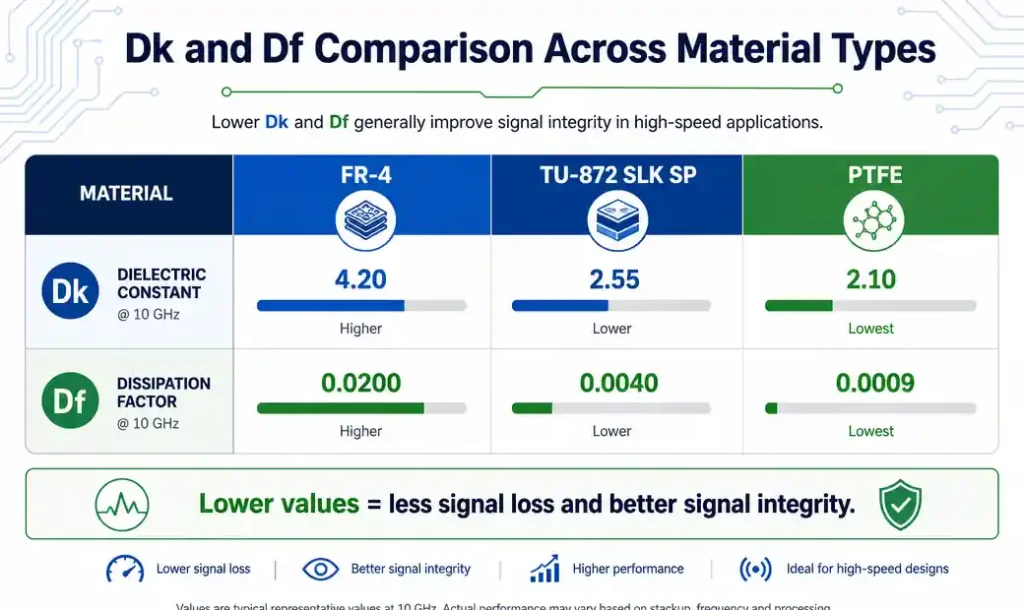
For modern applications like 5G mmWave, 77 GHz automotive radar, and 56 Gbps PAM4 signaling, traditional FR-4 materials simply cannot deliver the performance needed. Their Dk values (typically 4.2-4.5) and Df values (0.015-0.020 at 10 GHz) introduce excessive losses that compromise system performance.
This is where specialized low-loss materials like TU-872 SLK SP come into play, offering Dk values around 3.0 and Df values below 0.003, dramatically improving signal integrity while reducing power consumption.
What is TU-872 SLK SP Material?
TU-872 SLK SP is an advanced thermoset resin-based laminate material specifically engineered for high-frequency and high-speed digital applications. The “SLK” designation indicates its super-low-loss characteristics, while “SP” refers to its special processing capabilities that enable reliable manufacturing.
This material belongs to the family of modified epoxy or polyphenylene oxide (PPO) based laminates that have been optimized to achieve an exceptional balance between electrical performance, thermal stability, and manufacturability.
Key Material Composition:
- Low-loss resin system with controlled dielectric properties
- High-quality E-glass or specialized glass fabric reinforcement
- Optimized filler materials to achieve target Dk/Df values
- Thermal stabilizers for reliable operation across temperature ranges
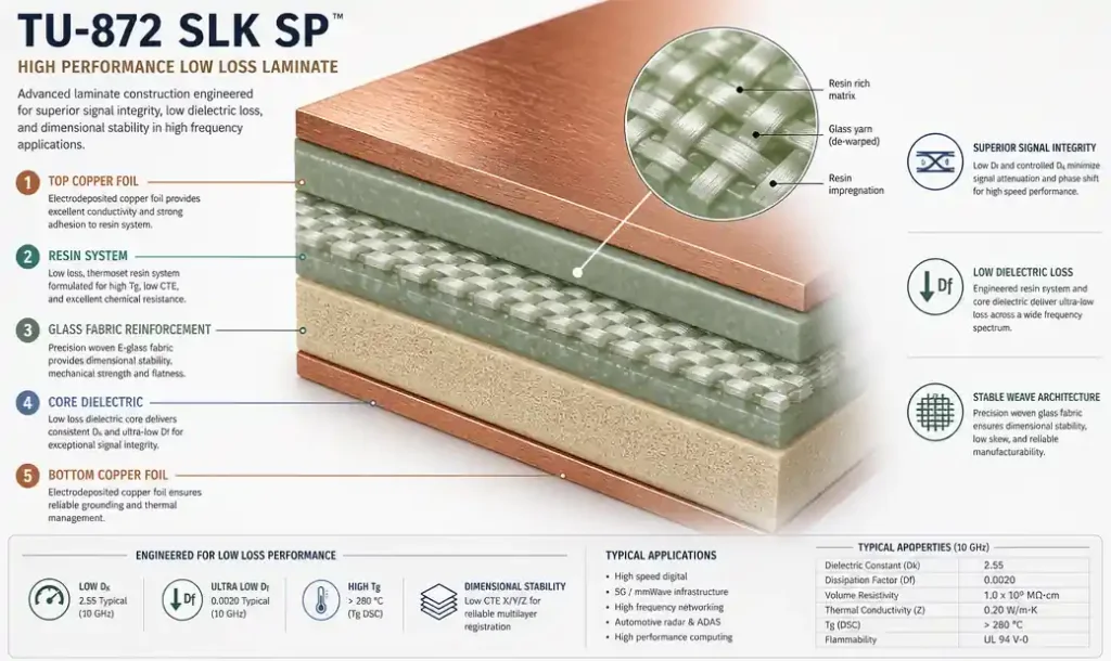
Unlike PTFE-based materials that offer excellent electrical properties but challenging processing, TU-872 SLK SP uses conventional PCB manufacturing processes. This means you can achieve near-PTFE performance without the need for specialized drilling, plating, or lamination equipment.
The material is available in various thicknesses and copper weights, making it suitable for both rigid and multilayer PCB constructions. Its compatibility with standard FR-4 processing equipment significantly reduces manufacturing costs while maintaining high performance.
Key Electrical Properties of TU-872 SLK SP
Understanding the electrical characteristics of TU-872 SLK SP is essential for making informed design decisions. Here are the critical specifications that set this material apart:
Dielectric Constant (Dk):
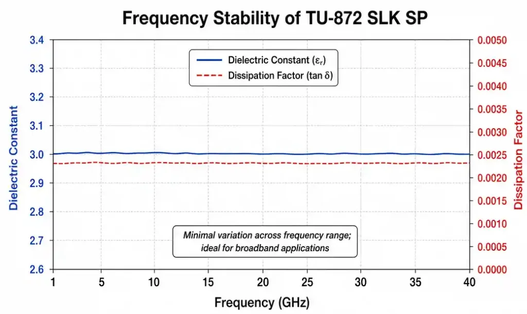
- Typical value: 3.0 ± 0.05 at 10 GHz
- Frequency stability: Minimal variation from 1 GHz to 40 GHz
- Temperature coefficient: Low Dk drift across -55°C to +125°C operating range
Dissipation Factor (Df):
- Typical value: 0.0025 at 10 GHz
- Ultra-low loss performance maintained across frequency spectrum
- Consistent performance even at elevated temperatures
Thermal Properties:
- Glass transition temperature (Tg): 180°C or higher
- Decomposition temperature (Td): >340°C
- Coefficient of thermal expansion (CTE): Matched to copper for reliability
- Thermal conductivity: Adequate for heat dissipation in most applications
Mechanical Properties:
- Flexural strength: Excellent for handling and assembly
- Peel strength: Strong copper adhesion for reliable interconnects
- Dimensional stability: Minimal warpage during processing
Moisture Absorption:
- Low moisture uptake (<0.1%) ensures stable electrical properties
- Maintains performance in humid environments
These properties make TU-872 SLK SP particularly well-suited for applications where signal integrity cannot be compromised, such as high-speed backplanes, RF front-ends, and millimeter-wave antenna arrays.
Performance Advantages for High-Speed Applications
The superior electrical properties of TU-872 SLK SP translate into tangible performance benefits for high-speed designs:
Reduced Signal Loss:
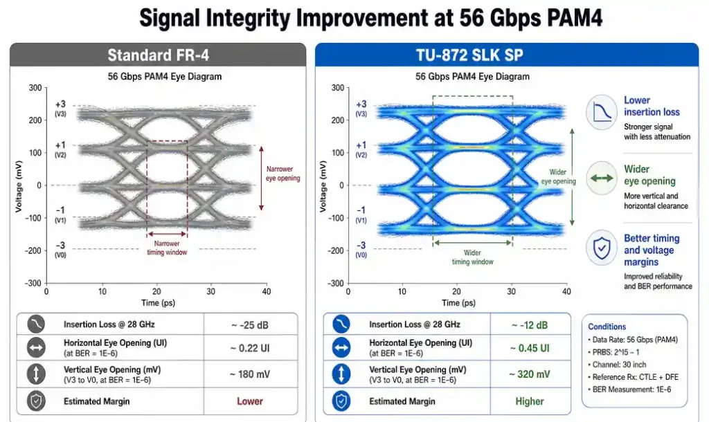
At 28 GHz, TU-872 SLK SP exhibits insertion loss approximately 40-50% lower than standard FR-4. This means signals can travel longer distances without requiring repeaters or amplifiers, simplifying system architecture and reducing power consumption.
Improved Signal Integrity:
Lower Dk values result in faster signal propagation and reduced impedance discontinuities. This minimizes reflections, crosstalk, and timing skew—critical factors in multi-gigabit serial links and parallel bus architectures.
Enhanced Bandwidth:
The flat Dk and Df response across frequency enables wider usable bandwidth. Your design can support higher data rates without encountering material-induced limitations.
Lower Power Consumption:
Reduced dielectric losses mean less signal energy is converted to heat. This translates to lower power requirements for transmitters and improved thermal management, particularly important in dense, high-power systems.
Better Eye Diagrams:
In high-speed serial applications (PCIe Gen5, USB4, 100G Ethernet), TU-872 SLK SP helps maintain open eye diagrams with adequate margins, ensuring reliable bit error rates even at maximum data rates.
Consistent Performance:
Unlike some materials where properties degrade with temperature or humidity, TU-872 SLK SP maintains stable electrical characteristics across environmental conditions, ensuring reliable operation in automotive, aerospace, and industrial applications.
Comparing TU-872 SLK SP with Other Low-Loss Materials
To appreciate TU-872 SLK SP’s position in the market, let’s compare it with other popular low-loss materials:
TU-872 SLK SP vs. Standard FR-4:
- Dk: 3.0 vs. 4.3 (30% lower)
- Df: 0.0025 vs. 0.018 at 10 GHz (86% lower)
- Cost: 3-4x higher but justified for high-frequency applications
- Processing: Similar manufacturing processes
TU-872 SLK SP vs. Rogers RO4350B:
- Dk: 3.0 vs. 3.48 (slightly lower)
- Df: 0.0025 vs. 0.0037 at 10 GHz (comparable)
- Cost: Generally competitive
- Processing: Both use standard FR-4 processes
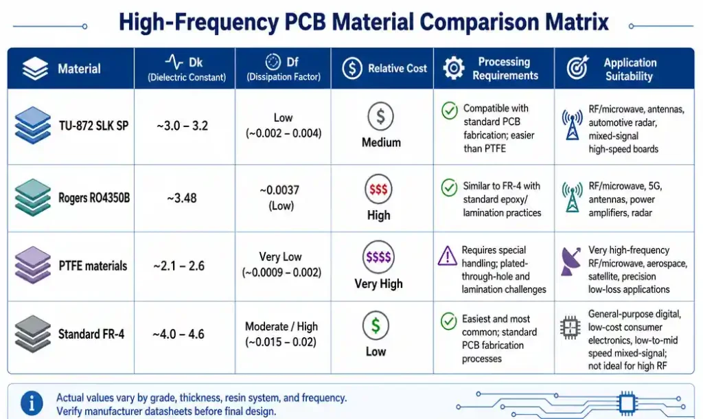
TU-872 SLK SP vs. PTFE-based Materials (Rogers RT/duroid):
- Dk: 3.0 vs. 2.2-3.0 (comparable range)
- Df: 0.0025 vs. 0.0009-0.0020 (PTFE slightly better)
- Cost: TU-872 SLK SP significantly more economical
- Processing: TU-872 SLK SP uses standard processes; PTFE requires specialized equipment
TU-872 SLK SP vs. Isola Astra MT77:
- Dk: 3.0 vs. 3.0 (equivalent)
- Df: 0.0025 vs. 0.0017 at 10 GHz (Astra MT77 slightly better)
- Cost: Comparable
- Processing: Both compatible with standard manufacturing
The key advantage of TU-872 SLK SP is its optimal balance between electrical performance, manufacturability, and cost. While PTFE materials offer marginally better electrical properties, their processing challenges and higher costs make TU-872 SLK SP the practical choice for most high-volume applications.
Design Considerations and Best Practices
Successfully implementing TU-872 SLK SP requires attention to several design factors:
Impedance Control:
With Dk of 3.0, trace geometries will differ from FR-4 designs. Use your PCB design software’s stackup calculator or field solver to accurately determine trace widths for target impedances (typically 50Ω single-ended, 100Ω differential).
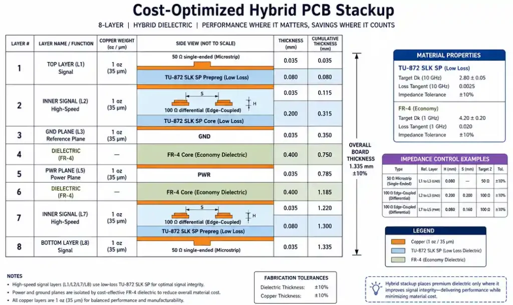
Stackup Design:
- Consider hybrid stackups: Use TU-872 SLK SP for high-speed signal layers and standard FR-4 for power/ground planes to optimize cost
- Maintain symmetry to minimize warpage
- Plan for thinner dielectrics to achieve controlled impedances with reasonable trace widths
Via Design:
- Use back-drilling or blind/buried vias to minimize stub resonances
- Optimize via pad sizes to reduce parasitic capacitance
- Consider via-in-pad designs for high-density layouts
Thermal Management:
While TU-872 SLK SP has adequate thermal conductivity, high-power designs may benefit from:
- Thermal vias connecting to ground planes
- Copper coin or metal core integration for heat-intensive areas
- Adequate spacing around high-power components
Signal Routing:
- Minimize trace length for critical high-speed signals
- Maintain consistent trace widths to avoid impedance discontinuities
- Use appropriate corner mitigation (chamfered or curved corners for >10 GHz)
- Provide adequate spacing between traces to minimize crosstalk
Simulation and Verification:
- Perform pre-layout signal integrity simulations using accurate material models
- Validate impedance with TDR measurements on test coupons
- Conduct post-layout electromagnetic simulation for critical nets
Design for Manufacturing:
- Follow your fabricator’s design rules for minimum trace/space
- Provide clear stackup documentation with material specifications
- Include impedance test coupons on production panels
Manufacturing and Processing Guidelines
One of TU-872 SLK SP’s key advantages is its compatibility with standard PCB manufacturing processes. However, some considerations ensure optimal results:
Drilling:
- Standard carbide drill bits work well
- Use appropriate feed rates and spindle speeds per fabricator recommendations
- Entry and backup materials should be compatible with the laminate
Desmear and Preparation:
- Standard desmear processes are effective
- Plasma treatment may enhance copper adhesion
- Follow material supplier’s recommendations for optimal surface preparation
Plating:
- Conventional electroless and electrolytic copper plating processes apply
- No special chemistry required compared to FR-4
- Maintain proper plating thickness for impedance control
Lamination:
- Press cycles similar to FR-4 but follow material datasheet specifications
- Typical lamination temperatures: 180-200°C
- Pressure and dwell time per supplier recommendations
- Hybrid stackups with FR-4 are feasible with proper press cycle optimization
Surface Finish:
- Compatible with all standard finishes: HASL, ENIG, ImAg, OSP, ENEPIG
- ENIG or ENEPIG recommended for high-frequency applications to minimize skin effect losses
Quality Control:
- Impedance testing on every production panel recommended
- Microsectioning to verify layer registration and resin flow
- Thermal stress testing for reliability validation
Storage and Handling:
- Store in controlled humidity environment (<50% RH)
- Bake before lamination if material has been exposed to humidity
- Handle with care to avoid contamination of bonding surfaces
Real-World Applications and Use Cases
TU-872 SLK SP has proven itself across diverse high-performance applications:
5G Infrastructure:
- Massive MIMO antenna arrays requiring low-loss feed networks
- mmWave base station RF front-ends (24-40 GHz)
- High-speed backhaul and fronthaul interconnects
Automotive Radar:
- 77 GHz and 79 GHz radar modules for ADAS and autonomous driving
- Low-loss antenna substrates for extended detection range
- Reliable performance across automotive temperature extremes (-40°C to +125°C)
High-Speed Computing:
- Server backplanes with 56 Gbps PAM4 signaling
- PCIe Gen5 and Gen6 interconnects
- 100G/400G Ethernet switch fabrics
Aerospace and Defense:
- Phased array radar systems
- Satellite communication terminals
- Electronic warfare systems requiring wide bandwidth
Test and Measurement:
- High-frequency test fixtures and probe cards
- Network analyzer calibration substrates
- Signal integrity test boards
Consumer Electronics:
- High-end WiFi 6E and WiFi 7 routers (6 GHz operation)
- 5G smartphones and tablets
- Ultra-wideband (UWB) devices
In each application, TU-872 SLK SP enables designers to meet stringent performance requirements while maintaining manufacturability and cost-effectiveness.
Cost-Benefit Analysis
While TU-872 SLK SP costs more than standard FR-4, the total system value proposition is compelling:
Material Cost Premium:
- Typically 3-4x the cost of FR-4 per square foot
- Comparable to other mid-tier low-loss materials
- Significantly less expensive than PTFE-based materials
Manufacturing Cost Impact:
- No premium for processing (unlike PTFE materials)
- Standard fabrication equipment and processes
- Shorter lead times compared to exotic materials
System-Level Savings:
- Reduced need for signal conditioning components (retimers, equalizers)
- Lower power consumption reduces cooling requirements
- Fewer layers possible due to better signal integrity
- Extended transmission distances without repeaters
Reliability Benefits:
- Stable performance across temperature and humidity
- Lower failure rates in field deployment
- Reduced warranty costs
Time-to-Market:
- Faster design iterations with predictable material behavior
- Readily available from multiple suppliers
- Established supply chain reduces procurement risk
For high-frequency applications above 10 GHz or high-speed digital designs above 25 Gbps, the performance benefits of TU-872 SLK SP typically justify the material cost premium. The key is to use it strategically—applying it only to critical signal layers while using standard materials for power and ground planes.
Future Trends in Low-Loss PCB Materials
The PCB materials landscape continues to evolve rapidly, driven by increasing data rates and frequency requirements:
Emerging Technologies:
- 6G research pushing frequencies to 100+ GHz
- 224 Gbps PAM4 signaling for next-generation data centers
- Terahertz applications in imaging and sensing
Material Development Trends:
- Even lower Dk values (approaching 2.5) for faster signal propagation
- Df values below 0.002 at millimeter-wave frequencies
- Improved thermal conductivity for high-power applications
- Enhanced dimensional stability for large-format boards
Sustainability Focus:
- Halogen-free formulations meeting environmental regulations
- Recyclable materials and circular economy approaches
- Reduced energy consumption in manufacturing
Advanced Manufacturing:
- Materials optimized for additive manufacturing (3D printed electronics)
- Embedded component integration
- Ultra-thin dielectrics for high-density interconnect
Hybrid and Heterogeneous Integration:
- Materials compatible with chiplet packaging
- Organic interposers for 2.5D/3D integration
- Co-design of materials with semiconductor processes
TU-872 SLK SP represents the current state-of-the-art in balancing performance, manufacturability, and cost. As requirements continue to push boundaries, we can expect continued innovation in low-loss materials, but the fundamental principles of low Dk/Df selection will remain critical for high-speed design success.
Conclusion
TU-872 SLK SP material offers an exceptional combination of low dielectric constant (Dk ~3.0) and ultra-low dissipation factor (Df ~0.0025) that makes it ideal for high-speed PCB applications. Its compatibility with standard manufacturing processes, stable electrical properties across frequency and temperature, and cost-effectiveness compared to PTFE materials position it as a go-to choice for 5G, automotive radar, high-speed computing, and other demanding applications.
When selecting materials for your next high-frequency design, consider TU-872 SLK SP if you need:
- Operating frequencies above 10 GHz
- Data rates exceeding 25 Gbps
- Extended signal transmission distances
- Reliable performance across environmental conditions
- Cost-effective manufacturing at volume
By understanding the material properties, design considerations, and application requirements outlined in this guide, you can make informed decisions that optimize both electrical performance and project economics.
Frequently Asked Questions
Q: Can TU-872 SLK SP be mixed with FR-4 in the same stackup?
A: Yes, hybrid stackups are common and cost-effective. Use TU-872 SLK SP for critical high-speed signal layers and FR-4 for power/ground planes. Work with your fabricator to optimize the press cycle.
Q: What is the typical lead time for TU-872 SLK SP material?
A: Lead times vary by supplier and region but typically range from 2-4 weeks for standard thicknesses. Custom constructions may require longer lead times.
Q: How does TU-872 SLK SP perform at millimeter-wave frequencies (>30 GHz)?
A: TU-872 SLK SP maintains excellent performance through 40 GHz with stable Dk and low Df. For frequencies above 60 GHz, consider PTFE-based materials for optimal performance.
Q: Is special design software required for TU-872 SLK SP?
A: No special software is needed. Standard PCB design tools work well. Ensure your field solver has accurate material models—contact the material supplier for Dk/Df data files.
Q: What surface finish is recommended for high-frequency applications?
A: ENIG (Electroless Nickel Immersion Gold) or ENEPIG provides excellent high-frequency performance with minimal skin effect losses. Avoid HASL for impedance-controlled designs due to surface roughness.