
What is Rigid-Flex PCB Lifespan? Reliability Testing and Validation
Rigid-flex PCB assemblies in medical implants demonstrate operational lifespans exceeding 15 years with failure rates 8× lower than conventional connector-based systems. Yet achieving this reliability demands rigorous testing protocols that most engineers overlook until field failures emerge.
Understanding rigid-flex PCB lifespan requires examining accelerated life testing methodologies, thermal cycling validation, bend cycle endurance, and the IPC-6013 qualification framework that separates designs that last from those that fail prematurely.
What Determines Rigid-Flex PCB Lifespan?
Rigid-flex PCB lifespan is determined by mechanical stress at rigid-flex transition zones, thermal expansion mismatch, copper fatigue in flex regions, and solder joint integrity under repeated cycling. Unlike traditional rigid PCB assemblies, rigid-flex circuits experience unique failure modes from bending, twisting, and differential thermal expansion between rigid FR4 and flexible polyimide sections.
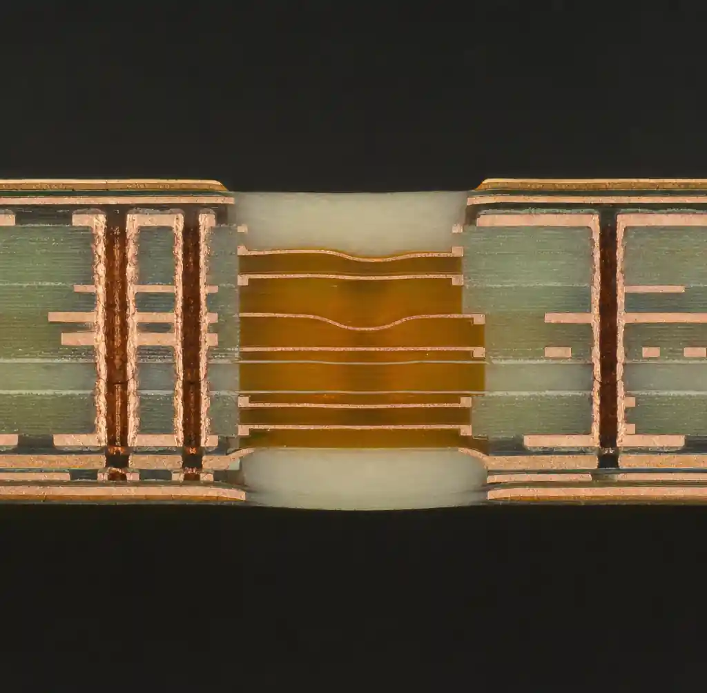
The primary lifespan-limiting factors include copper cracking in flex zones after repeated bending, delamination at rigid-flex boundaries due to CTE mismatch, via barrel fractures in transition regions, and solder joint fatigue from mechanical stress. Medical device rigid-flex assemblies target 7-15 year operational life, while aerospace applications demand 20-25 year service with zero failures.
According to IPC-6013 standards, rigid-flex PCBs must pass qualification testing that addresses these unique mechanical stresses before production release.
IPC-6013 Qualification Standards
IPC-6013 is the performance specification that defines acceptance criteria specifically for flexible and rigid-flex printed boards. This standard addresses failure modes that rigid board specifications like IPC-6012 cannot capture, including repeated bending, vibration in confined spaces, and mechanical fatigue at solder joints.
| IPC Class | Application | Defect Tolerance | Typical Use |
|---|---|---|---|
| Class 1 | General electronics | Cosmetic defects acceptable | Consumer products |
| Class 2 | Dedicated service | Limited defects allowed | Industrial controls, telecom |
| Class 3 | High reliability | Zero defects in critical areas | Medical, aerospace, military |
For life-critical applications, Class 3 certification is mandatory. This requires enhanced thermal stress testing, tighter manufacturing tolerances (±5% vs ±10%), stricter visual inspection criteria, and validated testing of transition zones where rigid meets flex. The IPC-6013 inspection framework defines specific acceptance limits for plating quality, copper thickness uniformity (minimum 25 micron in plated holes), and mechanical integrity at bend regions.
Critical Reliability Testing Methods
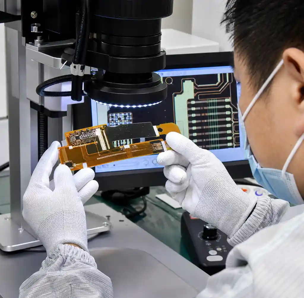
Rigid-flex reliability validation combines mechanical, thermal, and electrical testing to simulate years of field service in accelerated timeframes.
Essential Test Methods:
Dynamic Flex Cycling — Validates bend fatigue life by flexing the circuit through specified radius and angle for target cycle count. Medical wearables require 100,000+ cycles, while industrial hinges target 1,000,000+ cycles. Per IPC-6013, testing continues until electrical failure or visible cracking occurs.
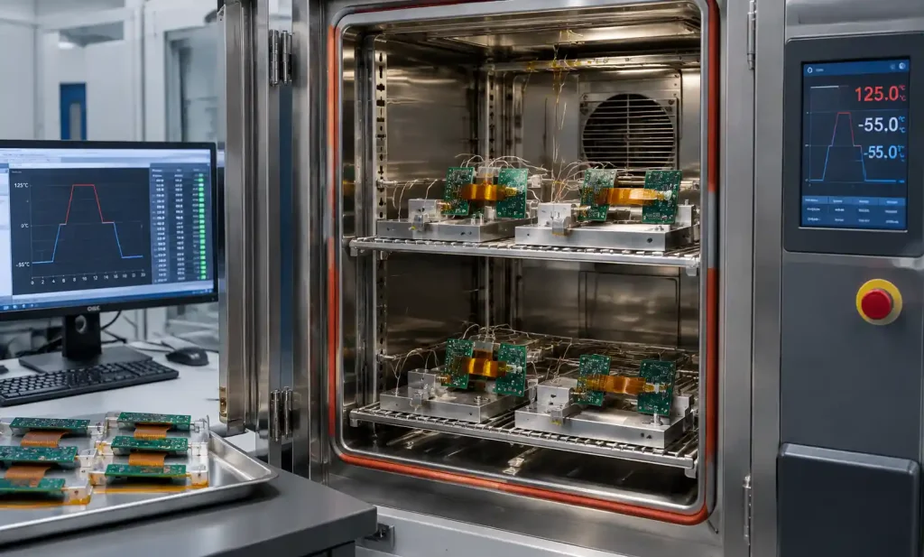
Thermal Cycling — Exposes rigid-flex assemblies to temperature extremes (-55°C to +125°C for industrial, +36°C to +42°C for implantables) to validate solder joint integrity and detect delamination. Standard profiles include 500-1000 cycles with 15-minute dwell times. This reveals CTE mismatch failures between rigid and flex sections.
Peel Strength Testing — Measures coverlay and copper adhesion to polyimide substrate. Minimum peel strength of 7 N/cm for adhesiveless construction and 5 N/cm for adhesive-based construction per IPC-TM-650 test method 2.4.9. Low peel strength indicates impending delamination.
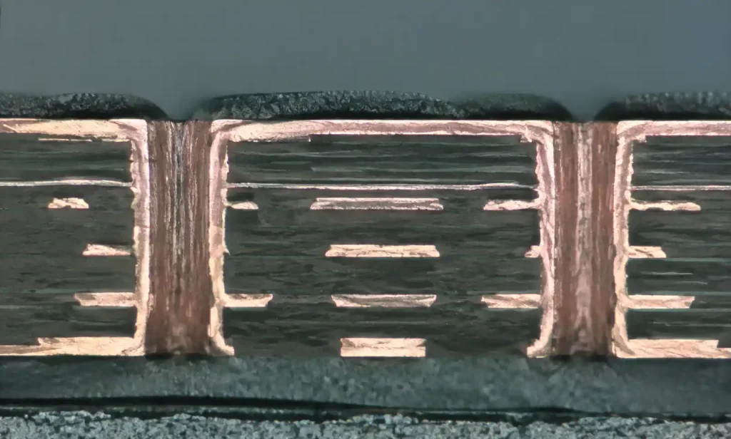
Microsection Analysis — Cross-sectional examination reveals copper cracking, via barrel integrity, and layer-to-layer registration at transition zones. This destructive test validates internal construction quality that visual inspection cannot detect.
| Test Type | What It Validates | Pass Criteria | Standard |
|---|---|---|---|
| Dynamic flex cycling | Bend fatigue endurance | Target cycles without failure | IPC-6013 Type 2 |
| Thermal cycling | CTE stress, solder joints | No cracks after 500-1000 cycles | IPC-6013 |
| Peel strength | Adhesion integrity | ≥7 N/cm adhesiveless | IPC-TM-650 |
| Dielectric withstand | Insulation breakdown | 500V+ per layer | IPC-6013 |
Thermal Cycling and CTE Mismatch
Coefficient of thermal expansion (CTE) mismatch between rigid FR4 (14-17 ppm/°C) and flexible polyimide (12-16 ppm/°C) creates mechanical stress during temperature cycling. This differential expansion concentrates stress at rigid-flex transition zones, causing copper cracking and delamination over time.
The stress intensifies in multilayer rigid-flex designs where each material interface expands at different rates. During thermal cycling from -40°C to +125°C (typical automotive range), a 100mm rigid-flex assembly experiences 150-200 microns of differential movement between materials.
CTE Stress Mitigation Strategies:
Symmetric Stackup Design — Balance copper and dielectric layers around the neutral axis to minimize warping. Asymmetric constructions create bending bias that accelerates fatigue.
Gradual Transitions — Extend the rigid-flex transition zone over 2-3mm rather than abrupt material changes. This distributes stress over larger area and reduces peak strain.
Stiffener Placement — Stop rigid stiffeners 1-2mm before the flex zone begins. Stiffeners that extend into bend areas create stress concentration points that initiate cracks.
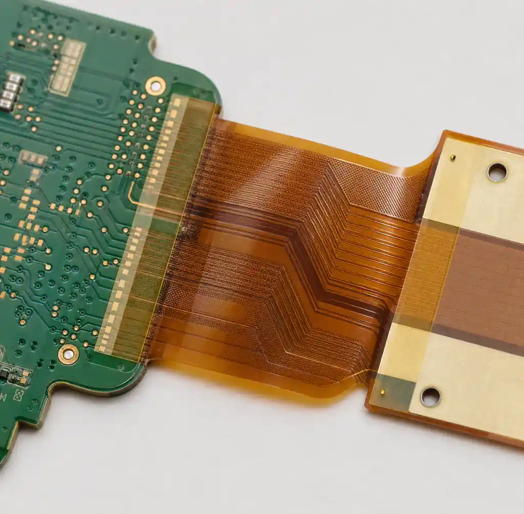
Via Management — Avoid plated through-holes within 1mm of rigid-flex boundaries. Vias in high-stress zones act as crack initiation sites under thermal cycling. Use HDI blind and buried vias in rigid sections to reduce transition zone complexity.
Testing data from semiconductor burn-in systems shows that optimized CTE management extends thermal cycling life by 3-5× compared to uncontrolled designs.
Bend Cycle Endurance Testing
Bend cycle testing validates dynamic flex reliability by repeatedly flexing the circuit through specified radius and angle until electrical failure occurs. This testing directly simulates real-world conditions for applications like wearable devices, medical instruments, and aerospace hinges.
Test Parameters:
- Bend Radius: Typically 10-50× total flex thickness depending on application
- Bend Angle: 90° to 180° depending on product geometry
- Cycle Rate: 30-60 cycles per minute
- Target Cycles: 100,000 for consumer, 1,000,000+ for industrial/medical
The copper type dramatically impacts bend life. Rolled-annealed copper withstands 10-20× more cycles than electrodeposited copper before cracking. For dynamic applications, specify ½oz to 1oz rolled-annealed copper in flex regions as detailed in our flex PCB design rules guide.

Failure Modes During Bend Testing:
Copper Fracture — Traces crack perpendicular to bend axis, typically at locations farthest from neutral axis. This is the most common failure mode, accounting for 60-70% of bend test failures.
Coverlay Cracking — Protective polyimide film cracks, exposing copper to environmental damage. Indicates excessive bend radius or improper coverlay adhesion.
Delamination — Copper separates from polyimide substrate. More common in adhesive-based construction versus adhesiveless.
Via Barrel Cracking — Plated through-holes fracture due to stress concentration. Avoid vias in bend zones entirely.
Per IPC-6013 Type 2 requirements, dynamic flex circuits must complete target cycle count with zero electrical failures and no visible cracking under 10× magnification.
Accelerated Life Testing (ALT) Protocols
Accelerated life testing applies stress conditions beyond normal operating parameters to identify potential weaknesses and predict field lifespan in compressed timeframes. HALT (Highly Accelerated Life Test) combines thermal extremes, rapid temperature cycling, and vibration to expose latent defects.
Standard ALT Profile for Rigid-Flex:
Temperature Step Stress — Increase temperature in 10°C steps from operational maximum to failure point. Dwell 10-15 minutes per step while monitoring electrical continuity. Identifies thermal limits and weak solder joints.
Rapid Thermal Cycling — Cycle between temperature extremes with <5 minute transition times (vs 15+ minutes in standard thermal cycling). This aggressive profile accelerates CTE-related failures.
Combined Environment Testing — Simultaneous thermal cycling + vibration mimics real-world aerospace and automotive environments. More effective at finding failures than sequential single-stress testing.
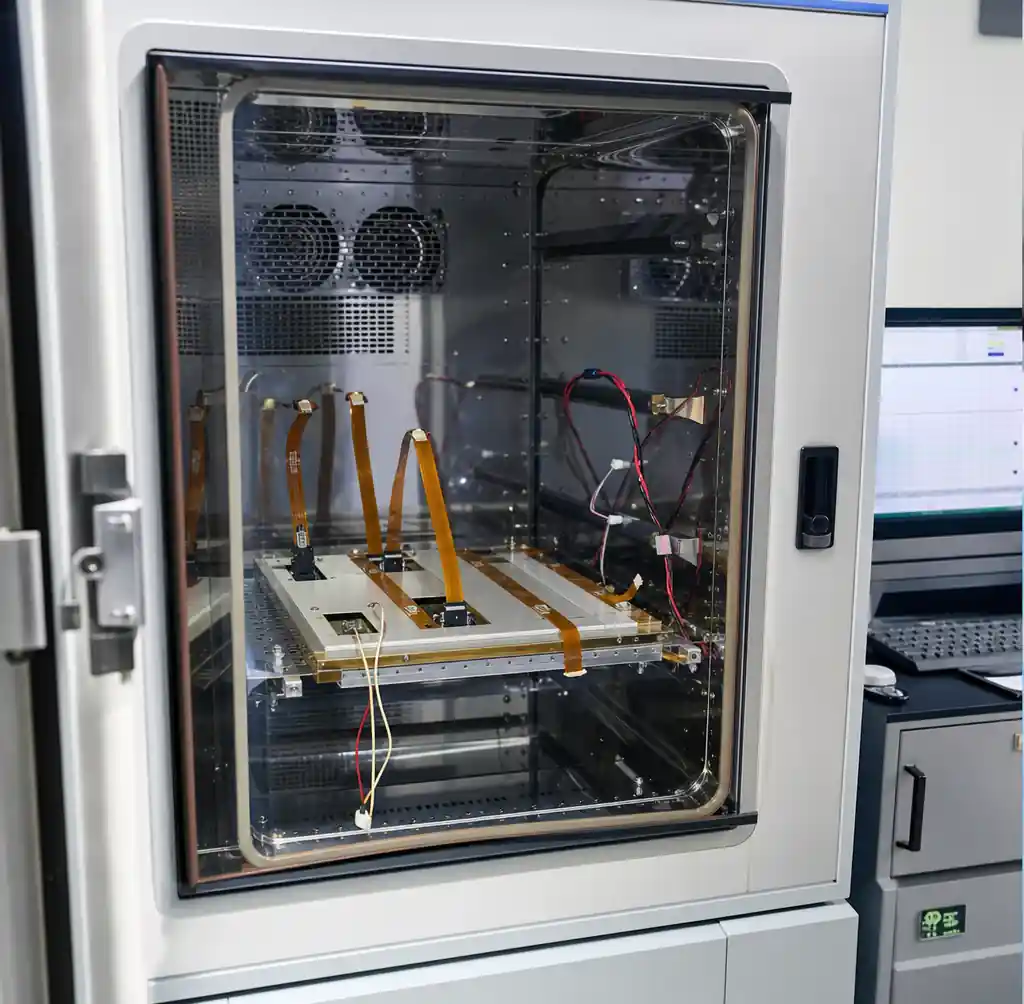
The relationship between accelerated stress and real-world life follows the Arrhenius equation for temperature-dependent failures and Coffin-Manson equation for fatigue-related failures. A common acceleration factor is 10-20×, meaning 1000 hours of ALT represents 10,000-20,000 hours of field service.
MTBF Prediction from ALT Data:
Mean time between failures (MTBF) for rigid-flex assemblies is calculated from ALT results using statistical models. Medical device rigid-flex typically targets >100,000 hours MTBF, while aerospace systems require >150,000 hours.
According to reliability testing research, proper ALT protocols reduce time-to-market by 6-12 months compared to real-time life testing while maintaining prediction accuracy within 15-20%.
MTBF Calculation for Rigid-Flex PCB
Mean Time Between Failures (MTBF) quantifies expected operational lifespan before the first failure occurs. For rigid-flex PCB assemblies, MTBF calculation considers copper fatigue, solder joint degradation, and material degradation under operating conditions.
MTBF Calculation Methods:
MIL-HDBK-217 — Military standard that predicts electronic component failure rates based on component type, operating temperature, and environmental stress. While useful for rigid PCB assemblies, this method underestimates mechanical failures specific to rigid-flex.
Weibull Analysis — Statistical method that models time-to-failure distribution from accelerated test data. More accurate for rigid-flex because it captures mechanical failure modes not covered in MIL-HDBK-217.
Physics of Failure (PoF) — Models actual failure mechanisms (copper fatigue, CTE stress, via cracking) rather than relying on historical data. Most accurate for novel rigid-flex designs without field history.
| Application | Target MTBF | Equivalent Service Life | Validation Method |
|---|---|---|---|
| Consumer wearables | 50,000 hours | 5-7 years | Weibull analysis + ALT |
| Medical implants | 120,000+ hours | 15+ years | PoF + clinical data |
| Aerospace avionics | 150,000+ hours | 20-25 years | MIL-HDBK-217 + HALT |
| Industrial controls | 80,000 hours | 10-12 years | Weibull + field data |
For automotive rigid-flex applications, AEC-Q100 qualification requires demonstrated 15-year service life under temperature cycling, vibration, and chemical exposure representative of underhood environments.
Application-Specific Lifespan Requirements
Different industries impose distinct lifespan and reliability requirements based on safety criticality, replacement costs, and regulatory frameworks.
Medical Devices — FDA Class III implantables require 15+ year demonstrated reliability with comprehensive ISO 13485 quality management. Testing includes body fluid exposure simulation (36-42°C in saline solution), biocompatibility validation, and sterilization cycle tolerance. Failure rates must remain below 0.1% over device lifetime.
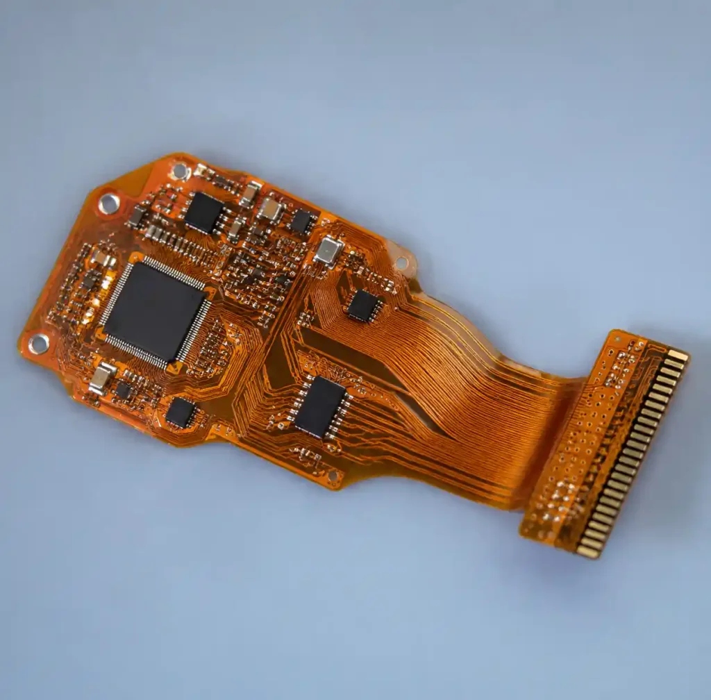
Aerospace and Defense — MIL-STD-810 environmental testing validates performance under extreme conditions: -55°C to +125°C temperature cycling, altitude simulation to 70,000 feet, shock and vibration per MIL-STD-202, and salt fog exposure. Target lifespan is 20-25 years with <0.01% failure rate. All materials must meet flammability requirements per FAA regulations.
Automotive Electronics — AEC-Q100 Grade 1 qualification requires operation from -40°C to +125°C with 1000+ thermal cycles, vibration testing per SAE J1211, and chemical resistance to fluids, oils, and cleaning agents. Electric vehicle applications demand 15-year service life matching vehicle warranty periods.
Industrial IoT — Operating temperature range -20°C to +70°C with 10-year minimum lifespan. Less stringent than medical or aerospace but requires resistance to dust, moisture (IP65-IP67), and electromagnetic interference in factory environments.
Consumer Electronics — Smartphones and wearables target 3-5 year lifespan with 100,000+ bend cycles for folding devices. Cost constraints limit testing scope compared to life-critical applications.
Design Factors That Impact Lifespan
Rigid-flex PCB lifespan is determined during design phase through material selection, stackup configuration, and transition zone management.
Critical Design Parameters:
Copper Weight and Type — Use ½oz to 1oz rolled-annealed copper in flex sections for dynamic applications. Heavier copper (2oz+) stiffens the flex and reduces bend life by 50-70%. Electrodeposited copper cracks 10× faster than rolled-annealed under repeated flexing.
Bend Radius — Minimum bend radius should be 10-20× total flex thickness for dynamic applications, 6× for static bends. Tighter radii exponentially reduce cycle life. A 4mm radius may last 18,000 cycles while an 8mm radius achieves 1,000,000+ cycles with identical construction.
Layer Count — Minimize layers in flex sections (typically 1-4 layers vs 8-20+ in rigid). Each additional flex layer increases thickness, stiffness, and strain on outer copper layers. Use HDI technology with blind/buried vias in rigid sections to reduce flex layer requirements.
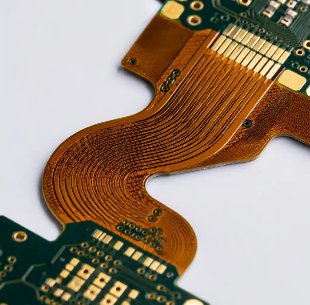
Transition Zone Design — Extend rigid-flex transition over 2-3mm with gradual stiffness change. Abrupt transitions concentrate stress and initiate cracks. Stop rigid stiffeners 1-2mm before bend zones begin.
Via Placement — Never place vias within bend radius or within 1mm of rigid-flex boundaries. Vias act as stress concentrators that initiate cracks. Use filled vias if unavoidable in flex sections.
Trace Routing — Route traces perpendicular to bend axis (90° to bend direction) to minimize tensile stress. Use curved traces instead of sharp 90° angles. Avoid solid copper pours in flex regions; use hatched patterns instead.
Material Selection — Specify polyimide substrate for applications requiring soldering or temperatures above 105°C. Use adhesiveless construction for dynamic flex and fine-line designs. Adhesive-based construction has lower peel strength and shorter bend life.
Following these design principles documented in our rigid-flex design guidelines prevents 70-80% of field failures and redesign cycles.
FAQs
What is the typical lifespan of a rigid-flex PCB?
Rigid-flex PCB lifespan ranges from 3-5 years for consumer electronics to 15+ years for medical implants and 20-25 years for aerospace applications. Actual lifespan depends on bend cycles, operating temperature range, environmental exposure, and design quality. Medical device rigid-flex assemblies demonstrate failure rates 8× lower than traditional connector-based systems when properly designed and tested per IPC-6013 Class 3 requirements.
What testing standards apply to rigid-flex PCB reliability validation?
IPC-6013 is the primary qualification standard for flexible and rigid-flex PCBs, defining acceptance criteria for transition zones, bend regions, and plating quality. Additional standards include IPC-6012 for rigid sections, ISO 13485 for medical devices, MIL-STD-810 for aerospace, and AEC-Q100 for automotive applications. Testing includes thermal cycling, bend cycle endurance, peel strength, and microsection analysis to validate construction quality and predict field life.
How many bend cycles should rigid-flex PCB withstand?
Consumer electronics target 100,000 bend cycles, industrial applications require 500,000-1,000,000 cycles, and medical instruments demand 1,000,000+ cycles. Actual bend life depends on bend radius (larger radius = more cycles), copper type (rolled-annealed lasts 10-20× longer than electrodeposited), copper weight (½oz to 1oz optimal), and trace routing (perpendicular to bend axis). Static flex designs only need to survive installation without subsequent flexing.
What causes rigid-flex PCB failures in the field?
The most common rigid-flex failures are copper cracking in flex zones (60-70% of failures), delamination at rigid-flex transition zones due to CTE mismatch, via barrel fractures from stress concentration, and solder joint fatigue from mechanical stress. These failures result from insufficient bend radius (<10× flex thickness), improper copper selection (electrodeposited instead of rolled-annealed), vias placed in bend zones, and abrupt rigid-flex transitions without stress relief.
How is MTBF calculated for rigid-flex PCB assemblies?
MTBF (Mean Time Between Failures) for rigid-flex PCB is calculated using Weibull analysis of accelerated life test data, Physics of Failure modeling of specific failure mechanisms, or MIL-HDBK-217 predictions. Medical device rigid-flex targets 120,000+ hours MTBF (15+ year life), aerospace requires 150,000+ hours, and industrial applications need 80,000 hours minimum. MTBF prediction accuracy improves when combining multiple methods and validating against field return data.
What accelerated testing methods predict rigid-flex lifespan?
HALT (Highly Accelerated Life Test) applies thermal extremes, rapid temperature cycling, and vibration simultaneously to expose weaknesses. Standard ALT protocols include temperature step stress testing, rapid thermal cycling with <5 minute transitions, combined environment testing (thermal + vibration), and dynamic flex cycling at 2-5× operational bend angle. Acceleration factors of 10-20× allow 1000 hours of testing to represent 10,000-20,000 hours of field service while maintaining prediction accuracy within 15-20%.
Conclusion
Rigid-flex PCB lifespan extends from 5 years in consumer devices to 25 years in aerospace applications when properly designed and validated. Achieving target reliability requires IPC-6013 Class 3 qualification testing, including thermal cycling, bend cycle endurance, and accelerated life testing that simulates years of field service in compressed timeframes.
The critical success factors are copper selection (rolled-annealed for dynamic flex), generous bend radius (10-20× flex thickness), proper transition zone design, and comprehensive testing per application requirements. Medical and aerospace rigid-flex assemblies demonstrate 8× lower failure rates than connector-based systems through elimination of mechanical interconnects and rigorous validation protocols.
If you need high-reliability rigid-flex PCB manufacturing with comprehensive testing and validation services, Andwin Circuits offers advanced capabilities up to 50 layers with ISO 9001, IATF 16949, and UL certification. Our engineering team provides design review, IPC-6013 Class 3 qualification testing, and accelerated life testing to ensure your rigid-flex assemblies meet target lifespan requirements for medical, aerospace, and industrial applications.
Contact us today for custom rigid-flex PCB solutions with validated reliability and competitive factory-direct pricing.