Rogers 4350B Copper Core PCB: Unlocking RF Performance and Extreme Thermal Conductivity
If you are designing high-power RF amplifiers, 5G base stations, or automotive radar systems, you are likely fighting a two-front war: maintaining pristine signal integrity at high frequencies while preventing your board from melting down under extreme thermal loads. Standard FR4 will fry, and standard aluminum cores often introduce signal loss or fail to dissipate heat fast enough.
The solution? The Rogers 4350B Copper Core PCB. By combining an industry-standard high-frequency laminate with a heavy metal base, engineers can achieve the “best of both worlds.” In this comprehensive guide, we will break down the thermal physics, explain how to avoid catastrophic delamination during manufacturing, and provide the exact data you need to make the right material choices for your next high-power RF project.
Understanding Rogers 4350B Copper Core PCBs: The
Basics
In the modern landscape of telecommunications and aerospace, power density is skyrocketing. Components are getting smaller, frequencies are getting higher (often pushing well into the millimeter-wave spectrum), and the heat generated per square inch is unprecedented.
When an RF power amplifier operates, it generates massive localized heat. If that heat is not evacuated immediately, the junction temperature of the semiconductor rises, leading to thermal throttling, shifted operating frequencies, and ultimately, premature component failure.
To solve this, engineers turn to advanced Metal Core PCB solutions. However, you cannot simply glue any dielectric to a piece of metal. You need a laminate that respects the delicate nature of high-speed radio waves.
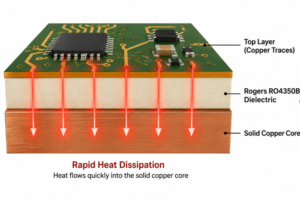
The Synergy of RO4350B and Copper:
- The Signal Highway: Rogers RO4350B is a hydrocarbon/ceramic laminate. It acts as a pristine, distortion-free highway for high-speed radio signals.
- The Heat Sink: The solid copper base acts as a massive thermal reservoir, pulling heat away from critical components exponentially faster than traditional substrates.
Core Concepts Simplified: Dk, Df, and Thermal Dynamics
Before diving into manufacturing complexities, we must understand the three critical metrics that dictate why this specific material combination is the gold standard for high-power RF design.
Dielectric Constant (Dk): The “Stable Highway”
The Dielectric Constant measures how much a material resists the formation of an electric field. For RF engineers, a fluctuating Dk is a nightmare—it causes signal phase shifts and impedance mismatches.
- The RO4350B Advantage: With a highly stable Dk of 3.48, RO4350B ensures that regardless of whether your board is operating in a freezing cell tower or a baking automotive radar housing, your radio signal will not get distorted or delayed.
Dissipation Factor (Df): The “Clear Glass Window”
Also known as signal loss or loss tangent. Imagine shining a flashlight through a window. Standard FR4 is like frosted glass—it absorbs and scatters the light (energy).
- The RO4350B Advantage: With an ultra-low Df of 0.0037, this laminate is like a perfectly clear glass window. It allows the RF signal’s energy to pass through with minimal absorption, maximizing the efficiency of your amplifiers.
Coefficient of Thermal Expansion (CTE): The “Peeling Sticker” Effect
This is where the engineering gets difficult. CTE is the rate at which a material expands when heated. Copper and ceramic/hydrocarbon laminates naturally expand at different rates. If a PCB manufacturer does not match the CTE of the RO4350B layer to the copper core, the internal stress will literally tear the board apart—warping the metal or peeling the copper traces off like a cheap sticker.
Understanding the differences in thermal management between various core materials is crucial. While aluminum is cheaper, copper is the undisputed king of heat transfer for high-power localized nodes.
Core Material Comparison Table
When evaluating substrates for extreme environments, especially high-temperature applications, procurement managers must weigh thermal conductivity against cost and manufacturability.
| Feature / Material | Standard Aluminum Core | Copper Core (with RO4350B) | Pure Ceramic (AlN) |
|---|---|---|---|
| Thermal Conductivity | ~237 W/m·K (Two-lane road) | ~400 W/m·K (Four-lane highway) | 170 – 230 W/m·K |
| RF Signal Loss (Df) | High (if using standard dielectric) | Ultra-Low (0.0037) | Ultra-Low |
| Mechanical Strength | Excellent | Excellent | Brittle / Fragile |
| Cost | Low | Medium to High | Very High |
| Best Use Case | LED Lighting, Power Supplies | 5G Amplifiers, Radar, High-Power RF | Aerospace, Extreme Miniaturization |
Takeaway: Copper has nearly double the thermal conductivity of aluminum, providing the extra “bandwidth” needed to dissipate heat from high-power 5G antennas.
Manufacturing Guide: Overcoming the Bonding Challenge
It is a common topic on engineering forums like r/PrintedCircuitBoard and r/RFElectronics: finding a manufacturer who can reliably bond RO4350B to a heavy metal core without delamination issues is notoriously difficult.
The standard aluminum PCB manufacturing process is relatively straightforward. However, bonding a high-frequency Rogers laminate to a thick copper plate requires specialized lamination cycles, precise pressure control, and the correct prepreg selection.
The Reliable Bonding Process (Step-by-Step)
- Surface Preparation: The copper core must be mechanically and chemically roughened to create a micro-porous surface. If the copper is too smooth, the prepreg will not adhere, leading to delamination under thermal stress.
- Prepreg Selection: You cannot use standard FR4 prepreg to bond RO4350B to copper, as it will ruin the RF performance. We utilize Rogers RO4450F™ prepreg, which is specifically designed to match the Dk/Df characteristics of the RO4350B core while providing exceptional adhesion to metal.
- Profiled Lamination Cycle: The stack-up is placed in a vacuum press. The temperature is ramped up precisely to allow the prepreg resin to flow and fill any micro-voids, followed by a controlled cooling cycle. If cooled too quickly, the CTE mismatch will cause the board to warp into a “potato chip” shape.
- Blind/Buried Vias (If Applicable): For complex RF designs requiring grounding directly to the copper core, laser drilling and specialized copper plating techniques are employed to ensure a solid electrical and thermal path.
Technical Specifications Data Sheet
When specifying your Rogers 4350B Copper Core board, use these parameters to ensure manufacturability:
| Specification | Recommended Value / Range | Notes |
|---|---|---|
| Dielectric Material | Rogers RO4350B™ | Hydrocarbon ceramic |
| Prepreg (Bonding Layer) | Rogers RO4450F™ | Maintains RF integrity |
| Copper Core Thickness | 1.0mm to 3.0mm | 1.5mm is industry standard |
| Dielectric Thickness | 10 mil, 20 mil, 30 mil | 20 mil offers a good balance of strength and RF performance |
| Surface Finish | ENIG, Immersion Silver, ENEPIG | Avoid HASL for RF (uneven surface ruins high-frequency signals) |
| Thermal Conductivity (Core) | ~400 W/m·K | Pure copper base |
Expert Tips & Common Pitfalls to Avoid
Drawing from years of manufacturing experience and analyzing failed boards sent to us by frustrated engineers, here are the most common pitfalls when designing and procuring Rogers copper core boards.
❌ Pitfall 1: Ignoring the Z-Axis CTE
While X and Y axis expansion causes warping, Z-axis expansion (thickness) destroys vias. If your design includes plated through-holes (PTH) connecting the top RF layer to the copper base, a severe CTE mismatch will crack the copper plating inside the via barrel during wave soldering or operation.
Expert Tip: Always verify that your manufacturer uses a lamination profile specifically tuned for Rogers + Copper to minimize residual internal stress before drilling.
❌ Pitfall 2: Using the Wrong Surface Finish
Many procurement managers select HASL (Hot Air Solder Leveling) to save money. For high-frequency RF, the “skin effect” means the signal travels on the very outer surface of the trace. HASL leaves a bumpy, uneven surface, causing massive signal loss at 5G frequencies.
Expert Tip: Specify ENIG (Electroless Nickel Immersion Gold) or Immersion Silver. These provide a perfectly flat surface, ensuring predictable impedance and minimal insertion loss.
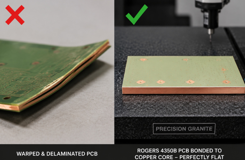
❌ Pitfall 3: Asymmetrical Stack-ups Causing Bow and Twist
Bonding a thin dielectric to a thick copper plate inherently creates an asymmetrical structure. When heated, the board wants to bow.
Expert Tip: While a true symmetrical stack-up isn’t possible with a single-sided metal core board, your manufacturer must use heavy-duty pressing plates and strictly controlled cool-down periods in the lamination press to guarantee the board meets the IPC-A-600 standard for bow and twist (typically <0.75%).
Conclusion & Final Thoughts
Designing hardware for the next generation of RF technology requires materials that refuse to compromise. The Rogers 4350B Copper Core PCB is not just an incremental upgrade; it is a mandatory architecture for systems that demand both high-fidelity signal transmission and extreme heat dissipation.
By understanding the synergy between RO4350B’s stable Dk/Df and copper’s 400 W/m·K thermal conductivity, and by partnering with a manufacturer who has mastered the complex prepreg bonding and CTE matching processes, you can eliminate thermal throttling and ensure the long-term reliability of your products.
Frequently Asked Questions (FAQ)
Q1: Why use a copper core with Rogers 4350B instead of standard aluminum?
A: Copper provides nearly double the thermal conductivity (~400 W/m·K vs ~237 W/m·K for aluminum), essential for dissipating extreme heat from high-power RF amplifiers. Combined with RO4350B’s ultra-low dissipation factor (Df 0.0037), this stack-up prevents thermal throttling while maintaining pristine signal integrity at 5G and millimeter-wave frequencies.
Q2: What prepreg should I use to bond RO4350B to a copper core?
A: Always use Rogers RO4450F™ prepreg, specifically engineered to match the Dk/Df characteristics of RO4350B while providing exceptional adhesion to metal. Standard FR4 prepreg will ruin RF performance and likely cause delamination under thermal stress.
Q3: Why is HASL surface finish bad for high-frequency RF PCBs?
A: HASL (Hot Air Solder Leveling) leaves a bumpy, uneven surface. At high frequencies, the skin effect causes signals to travel on the outer surface of traces—HASL’s irregular topography creates massive signal loss and impedance mismatch. Specify ENIG or Immersion Silver for perfectly flat surfaces.
Q4: How do I prevent delamination between RO4350B and the copper core?
A: Three critical steps: (1) mechanically/chemically roughen the copper core surface for micro-porous adhesion, (2) use matched CTE prepreg (RO4450F), and (3) implement a precisely controlled lamination cycle with gradual temperature ramp-up and controlled cool-down to minimize internal stress.
Q5: What causes “potato chip” warping in copper core PCBs?
A: Rapid cooling after lamination creates CTE mismatch stress between the copper base and dielectric layer. The board contracts unevenly and warps. Your manufacturer must use heavy-duty pressing plates and strictly controlled cool-down periods to maintain IPC-A-600 bow/twist standards (<0.75%).
Q6: Can I use plated through-holes (PTH) in Rogers copper core boards?
A: Yes, but with caution. Z-axis CTE mismatch can crack copper plating inside via barrels during thermal cycling. Always verify your manufacturer uses a lamination profile specifically tuned for Rogers + Copper to minimize residual stress before drilling, and consider laser-drilled microvias for direct grounding to the copper base.