
Basic points for PCB component welding
Before welding:
- Workbench: must be neat, clean, and anti-static. Anti-static tools/appliances should be used, and anti-static wrist straps should be worn.
- Tools: solder wire holders, component boxes, welding guns, soldering stations, tweezers, pliers and other welding tools and protective tools should be available.
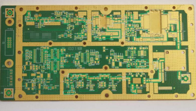
- Circuit board: Check the PCB board circuits for short circuits, open circuits, etc.
- Materials: Please confirm that it is the correct component, whether the component has polarity requirements, and whether the pads and component feet are oxidized. If so, use fine sandpaper to polish them clean before welding and apply flux.
During welding:
- Use the soldering iron safely and scientifically. The soldering iron should be grounded to prevent the component from being broken down due to leakage during welding. It is recommended to use a white light adjustable soldering iron. The temperature is about 350°C for lead soldering and about 380°C for lead-free soldering. If there is an oxide layer on the soldering iron tip, it needs to be wiped clean on a high-temperature sponge. Soldering irons should be tinned before use: Apply flux when the soldering iron is heated to the point where it can just melt the solder, and then apply the solder evenly on the tip of the soldering iron. Turn off the power of the soldering iron when not in use.
- Order of component soldering: The principle is that the components that are soldered first do not affect the soldering of the subsequent components. Generally, components with smaller volumes such as resistors and capacitors are soldered first, and components with larger volumes are soldered later, and connectors are soldered last.
- Placement of components on the board: They should be placed neatly, centered, and on the board surface, and pay attention to the polarity of the components.
- Soldering operation posture: The distance from the soldering iron to the nose should be 20 to 30 cm.
- Requirements during soldering: All components should be kept in place. Do not apply pressure to the soldering head. First, use solder to contact the solder joint, and then use the soldering iron tip to melt the solder in a 45° direction. After the solder melts and immerses the component pins, gently lift them up along the pins. The soldering takes about 2 to 3 seconds. Do not shake the components before the solder is completely solidified to avoid false soldering. Use flux appropriately.
- The welding time should not be too long, and repeated welding should be avoided as much as possible to avoid damaging the components.
After welding:
- Check for leaks, wrong welding (reverse polarity welding), short circuits, cold welding, etc.
- Check whether the solder joints have appropriate solder. The solder joints should be conical, full, smooth and uniform, without pinholes, shiny, without burrs, gaps and cracks, and the surface of the solder joints should be clean and free of rosin stains. The solder should surround the pins and should not be too much. If there are leads and pins, the length of the exposed pins should be between 1-2mm.
- The waste after welding should be cleaned up and thrown into the trash can in time.
- The welding tools should be put back in place after use.
- Use the washing water to clean the residues on the PCB board, such as tin slag, tin scraps, component feet, etc. Protective measures should be taken because the washing water is volatile and flammable. The remaining ones should be installed and placed properly, and do not waste them.
- Power-on test: First use the resistance range of the multimeter to measure whether there is a short circuit at the power input end. If there is, it should be eliminated before powering on. Then check the circuit according to the schematic diagram.
- After powering on, the IC must be assembled according to the list and then debugged. After completion, pack the PCB with an anti-static bag and do not place it at will.
Soldering specifications for mounted components:
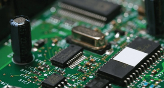
- Use tweezers to carefully place the SMD component on the PCB board, align it with the pad, and place it in the center with the component in the correct direction.
- Before welding, apply flux to the pad and treat it with a soldering iron to avoid poor tinning or oxidation. The component does not need to be treated.
- When welding, keep the soldering iron tip parallel to the pin to be soldered to prevent overlap due to excessive solder.
- When using a soldering iron to drag solder, the soldering iron can only slide lightly over the pin, otherwise it will bend the pin of the SMD component.
- After soldering all the pins, check the quality of the solder joints: the solder joints should be smooth, full and shiny, without any cold solder joints or leaking solder joints.