
Flex PCB Design Rules: Bend Cycles, Radius, and Material Selection
Most flex circuits do not fail on the bench. They fail six months into the field, when a hinge has folded 50,000 times and one copper trace finally cracks. The layout passed every electrical check, yet the board is dead.
That gap between “it works” and “it lasts” is where flex design lives. Bend radius, copper type, and stackup decide whether a flex PCB survives a single install or a million cycles. This guide covers the rules that actually move bend life, not the ones that just fill a datasheet.
The One Idea Behind Every Flex Rule
Bend a stackup and the outer surface stretches while the inner surface compresses. Somewhere between them sits the neutral axis, where strain is zero. Copper survives when it lives close to that axis and sees low strain; it cracks when it sits far from it under high strain.
Every rule below is really one goal in disguise: keep copper strain low. A larger radius, thinner copper, and a single flex layer all pull copper toward the neutral axis. That is why the same trace can last 500 cycles or 5 million depending on geometry.
Static vs Dynamic Flex
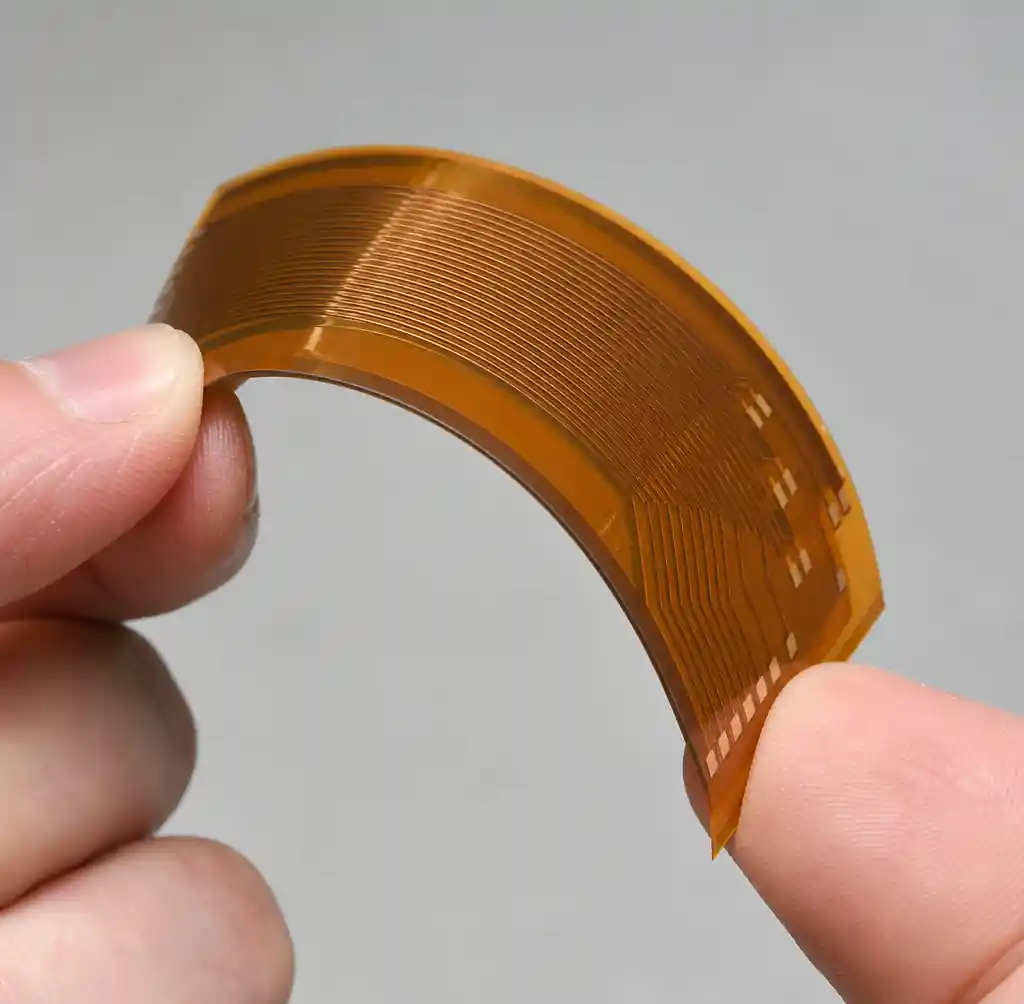
The first question is not “what radius?” It is “how many bends?” A static flex is folded once during assembly and never moves again. A dynamic flex flexes repeatedly in service, like a printhead ribbon or a laptop hinge.
This distinction changes every downstream choice. Static designs tolerate tight radii and cheaper builds because copper strains once. Dynamic designs demand generous radii, rolled copper, and single-layer routing because fatigue accumulates on every cycle.
Bend Radius Rules
Minimum bend radius scales with total flex thickness. Per IPC-2223 guidance, the ratios below are the working baselines fabricators design to. Thicker and more complex stacks need larger radii because copper sits farther from the neutral axis.
| Construction | Min Bend Radius | Typical Use |
|---|---|---|
| Single-sided flex | 3–6× thickness | One-time bends |
| Double-sided flex | 7–10× thickness | Static folds |
| Multilayer flex | 10–15× thickness | Rigid-flex transitions |
| Dynamic flex | 20–100× thickness | Repeated motion |
The multipliers look conservative until you see the cost of ignoring them. A dynamic layout routing 90-degree traces through a hinge at a 4mm radius can crack before 18,000 cycles. Open that radius and straighten the traces, and the same copper runs into the millions. Radius buys cycles exponentially, not linearly.
Material Selection: Polyimide vs PET
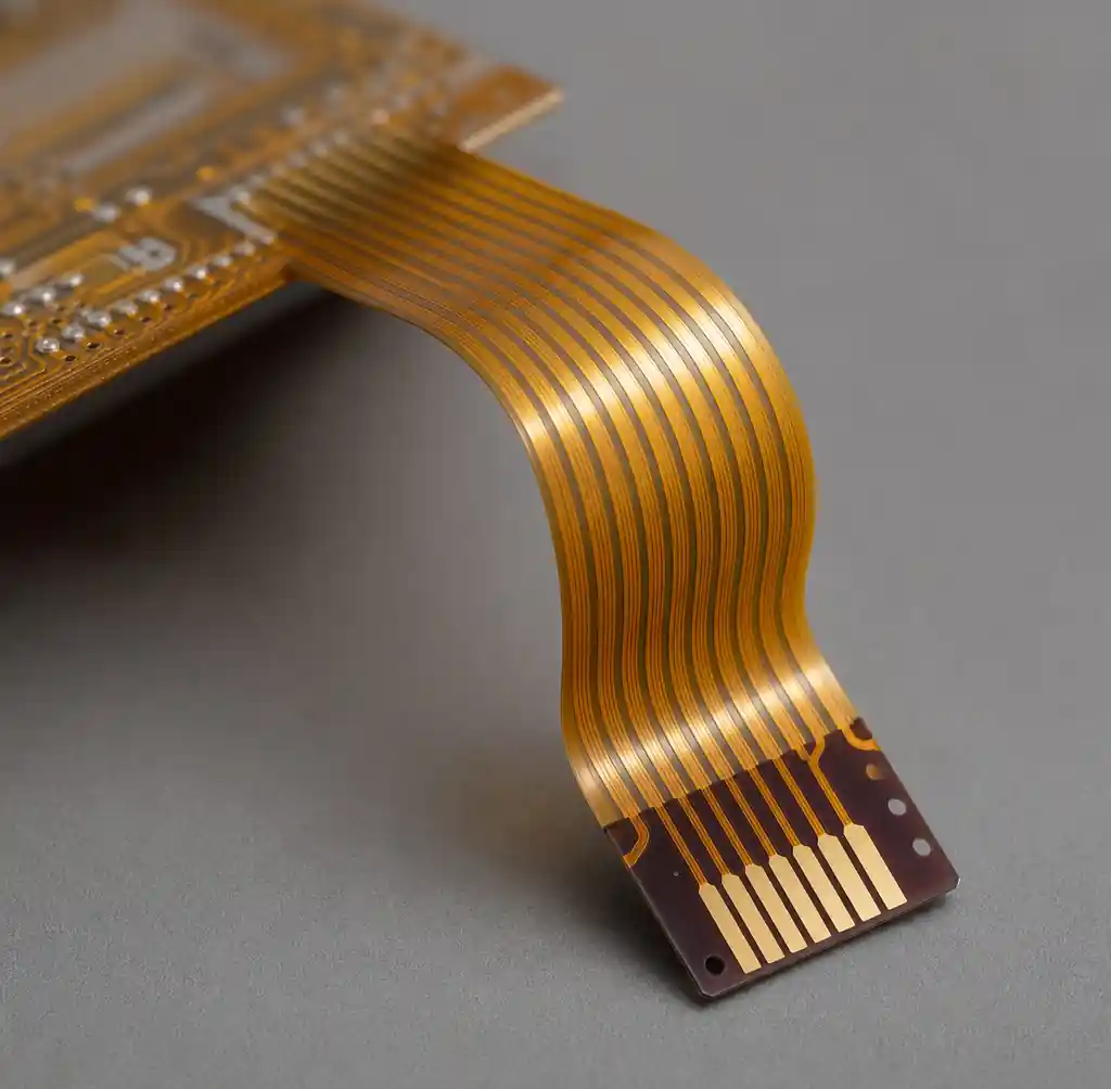
The substrate sets your thermal ceiling and your budget. Polyimide (PI) dominates roughly 80% of flex circuits because it survives soldering and high service temperatures. PET is cheaper but melts near reflow heat, so it lives in low-cost, low-temperature membrane work, not soldered assemblies.
Choosing the wrong film is an expensive mistake. PI costs several times more than PET, but a PET board that cannot take reflow is scrap before it ships.
| Property | Polyimide (PI) | PET |
|---|---|---|
| Max temp | ~200°C+ | ~105°C |
| Solderable | Yes | No |
| Flex life | Excellent | Fair |
| Relative cost | 3–5× | Baseline |
| Best fit | Soldered, dynamic, harsh | Low-cost static |
For any board that gets soldered or sees heat, specify PI. Reserve PET for simple, disposable, low-temperature circuits. See our PI vs PET material guide for the full breakdown.
Copper Type and Thickness
Copper type is the single biggest lever on dynamic bend life, and it is the one most layouts get wrong by default. Two foils exist: electrodeposited (ED) and rolled annealed (RA).
ED copper has fine, vertical grains that crack under repeated bending. RA copper is rolled into long grains aligned along the flex direction, so it resists fatigue far better. For any dynamic application, RA copper is not optional.
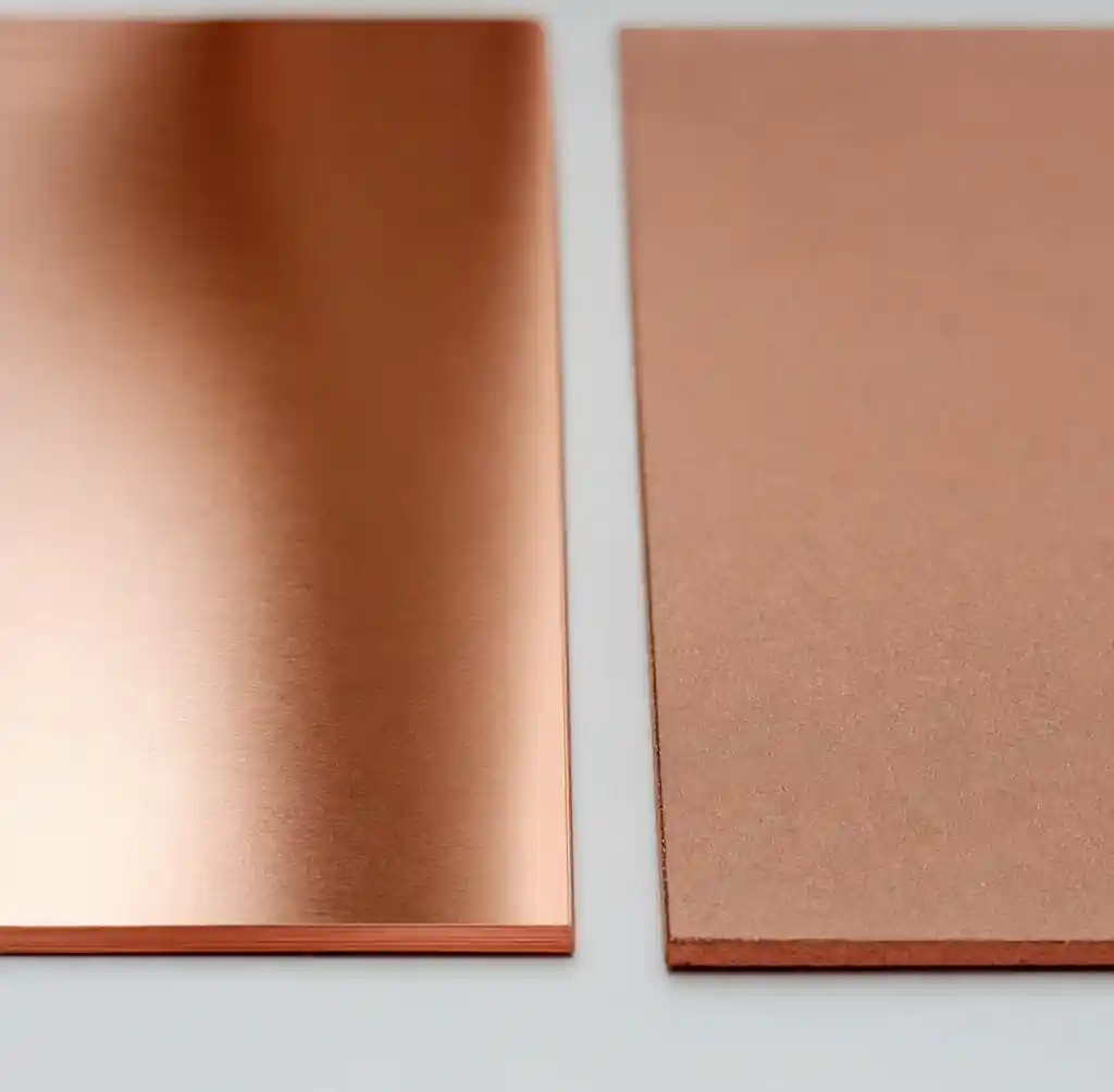
Thickness matters just as much. Thin copper, typically 1/2 oz (18µm), sits closer to the neutral axis and flexes freely. Heavier copper carries more current but stiffens the circuit and pushes strain up. In flex, you cannot simply add copper weight the way you would on a rigid board; more copper means a larger required radius and shorter bend life. Balance current needs against flexibility, and widen traces rather than thickening them where you can.
Adhesive, Adhesiveless, and Coverlay
How the layers are bonded quietly decides reliability. Adhesive-based construction glues copper to the film with an acrylic layer. It is cheaper, but that adhesive is the soft, high-expansion weak link that shears under repeated flexing and heat.
Adhesiveless construction bonds copper directly to the polyimide. It is thinner, handles heat better, and survives far more bend cycles, which makes it the standard for dynamic and fine-line work.
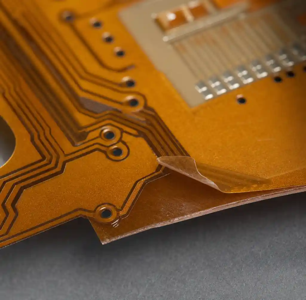
The coverlay, a polyimide film that replaces solder mask, needs the same discipline. Keep coverlay openings and stiffeners out of the bend zone; a hard edge there concentrates strain and starts cracks. Route traces straight and perpendicular across the bend, never turning inside it, and stagger traces on opposite layers so no two crack points line up.
Lifecycle Testing
A flex spec without a cycle count is incomplete. Dynamic reliability is proven, not assumed, so define the bend radius, cycle target, and flex angle up front, then validate against them.
| Test | What It Confirms | Standard |
|---|---|---|
| Dynamic flex cycling | Bend fatigue life | IPC-6013 |
| MIT/ductility fold | Copper flex endurance | IPC-TM-650 |
| Thermal cycling | Bond and via integrity | IPC-6013 |
Match the test to the product. A one-time install only needs an install-and-inspect check. A wearable hinge rated for years of daily motion needs cycling to its real target with margin. Ask your fabricator for the cycle data behind their rigid-flex capability, not just a pass or fail.
Design Best Practices
These steps prevent the failures that show up months after shipping:
- Decide static or dynamic before routing; it drives every other rule.
- Set bend radius from the ratio table, then round up for margin.
- Specify RA copper and thin foil (1/2 oz) for any repeated bending.
- Use adhesiveless PI for dynamic, high-temperature, or fine-line designs.
- Route traces straight and perpendicular through the bend, never at 90°.
- Keep coverlay openings, vias, and stiffeners out of the bend zone.
- Stagger traces across layers so crack points do not align.
- Define a cycle count and require test data to prove it.
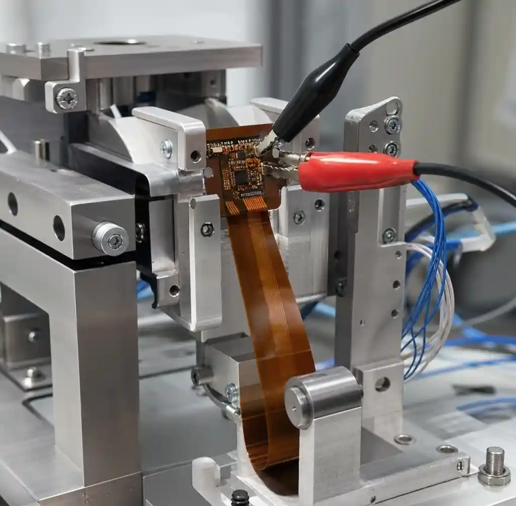
For the rigid-flex transition zone, where most cracks actually start, pair these with our rigid-flex design guidelines.
FAQs
What is the minimum bend radius for a flex PCB?
For static bends, 6× total thickness is the common floor. Dynamic applications need 20–100× depending on layer count, per IPC-2223 guidance.
Why use rolled annealed copper instead of electrodeposited?
RA copper has elongated grains aligned with the bend, giving far greater fatigue resistance. ED copper’s fine vertical grains crack quickly under repeated flexing.
Can I put vias or components in the bend area?
No. Vias, pads, and coverlay edges concentrate strain and become crack sites. Keep all of them in the rigid or non-bending zones.
Is polyimide always better than PET?
For soldered, dynamic, or high-temperature boards, yes. PET only makes sense for cheap, static, low-temperature circuits that are never reflowed.
Does thicker copper always improve a flex design?
No. Heavier copper adds current capacity but increases stiffness and required bend radius. For flexibility, keep copper thin and widen traces instead.
Conclusion
Flex reliability comes down to one habit: keep copper strain low, and prove it. Decide static or dynamic first, because that choice drives your radius, copper, and stackup. Then follow the ratio table, specify rolled annealed copper and adhesiveless polyimide for anything that moves, and keep vias and coverlay edges away from the bend. Finally, back the design with a real cycle target and test data, not a hopeful assumption. Get these right and a flex circuit lasts as long as the product around it.
Andwin Circuits manufactures single-layer to multilayer flex and rigid-flex PCBs up to 50 layers, with RA copper, adhesiveless polyimide, and IPC-6013 cycle testing, delivered in as fast as 7 days. Contact us today for flex PCB manufacturing and factory-direct pricing.