
MCPCB for Power Electronics: Design Guide for High Current Applications
In a power converter, the board is not a passive carrier. It is part of the cooling system. When a MOSFET or SiC device dumps 30, 50, or 100 watts into a few square millimeters, the substrate under it decides whether the junction sits at a safe 110°C or drifts toward thermal runaway.
Standard FR4 conducts heat at roughly 0.3 W/m·K. That is close to a thermal wall. This is why high-current designs move to a metal core PCB (MCPCB), where an aluminum or copper base pulls heat out from directly beneath the device. This guide covers the four decisions that actually matter for power work: base metal, dielectric, copper weight, and heat-sink coupling.
Why MCPCB for High-Current Power
An MCPCB stacks three layers: a copper circuit layer on top, a thin thermally conductive dielectric in the middle, and a solid metal base underneath. Heat flows from the component, straight down through the dielectric, into the base, and out to a heat sink or chassis.
The physics gap is large. A metal base moves heat about 500 to 1,300 times faster than FR4. That difference is what lets you run power and energy circuits like inverters, motor drives, and DC-DC converters at higher current density without the board becoming the failure point.
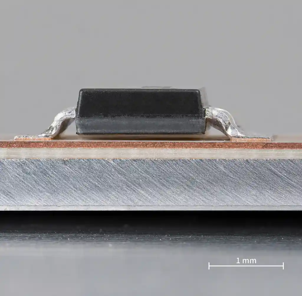
The catch most datasheets bury: the metal base is almost never the bottleneck. The dielectric is. We will get there, but first the base.
Base Metal: Aluminum vs Copper
Aluminum wins most power designs on cost, weight, and machinability. Copper wins when you need maximum heat spreading or want to route high current through the base itself. Copper conducts roughly 2 to 2.5 times better, but it costs more, weighs about three times as much, and is harder to fabricate.
| Property | Aluminum (5052/6061) | Copper (C1100) |
|---|---|---|
| Thermal conductivity | 140–200 W/m·K | 385–400 W/m·K |
| Relative cost | Baseline | 3–4× higher |
| Weight | Light | ~3× heavier |
| Typical use | LED, general power, EV | Extreme heat flux, RF power |
For most high-current designs, aluminum 5052 is the default. Reserve copper for dense power stages where every degree of junction temperature counts, such as SiC traction inverters.
The Dielectric Layer Is Your Real Bottleneck
The dielectric is a thin ceramic-filled polymer, typically 75 to 150 µm thick, that must insulate electrically while conducting heat. Because thermal resistance follows R = t / (k × A), a thick, low-conductivity dielectric quietly throttles your whole thermal path, no matter how good the base is.
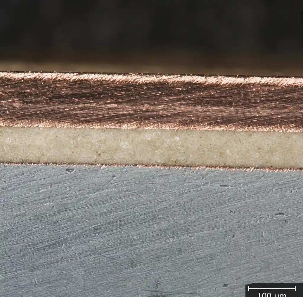
Standard dielectrics deliver about 1 to 2 W/m·K. High-performance grades reach 3 to 9 W/m·K. For example, Ventec VT-5A2 is rated 2.2 W/m·K and VT-4B5 reaches 4.2 W/m·K, while premium Henkel Bergquist and Laird formulations climb higher. The tradeoff is real: a thinner dielectric lowers thermal resistance but also lowers isolation voltage.
| Dielectric grade | Conductivity | Best fit |
|---|---|---|
| Standard | 1–2 W/m·K | LED, low-power drivers |
| Mid-range | 2–4 W/m·K | Motor drives, converters |
| High-performance | 4–9 W/m·K | SiC/GaN, high heat flux |
My rule for power boards: pick the dielectric first from your thermal budget, then verify isolation, not the other way around. Most thermal failures I see trace back to a designer specifying a base metal but leaving the dielectric as a default 100 µm standard grade.
Copper Thickness and Current Carrying
High current needs heavy copper. Where signal boards use 1 oz (35 µm), power MCPCBs commonly run 2 to 4 oz, and heavy-copper builds reach 6 to 10 oz for bus paths carrying tens of amps.
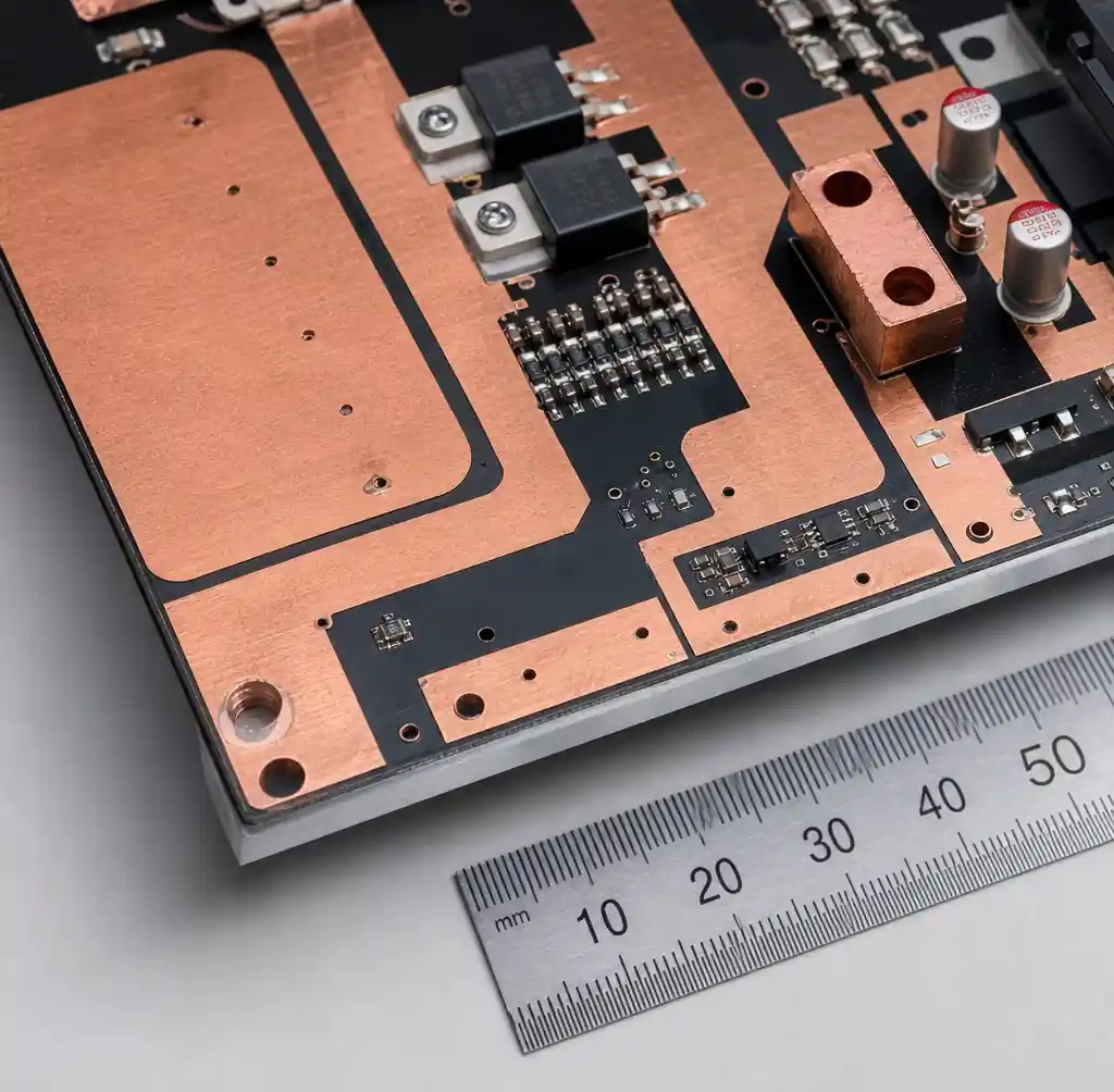
Size traces with IPC-2152, the current standard for current-carrying capacity. But know its limit: IPC-2152 does not model the metal base, so it under-predicts MCPCB ampacity. The base acts as a heat spreader, so a trace on an MCPCB carries meaningfully more current than the identical trace on FR4 at the same temperature rise. Treat the calculator as a conservative floor, then widen pours for margin.
| Copper weight | Thickness | Typical current path |
|---|---|---|
| 2 oz | 70 µm | Up to ~10 A |
| 3–4 oz | 105–140 µm | 10–30 A |
| 6–10 oz | 210–350 µm | Bus paths, 30 A+ |
Keep the design target rise modest, around 10 to 20°C, and pour wide copper under and around power devices to use the plane as a spreader.
Dielectric Strength and Isolation Voltage
Power designs often place a hot node millimeters from a grounded metal base, so isolation matters as much as heat. MCPCB dielectrics typically withstand 3,000 to 6,000 Vac hi-pot, tested per IPC-TM-650 2.5.7. The exact number scales with dielectric thickness and chemistry, so confirm it against your working voltage plus a safety margin.
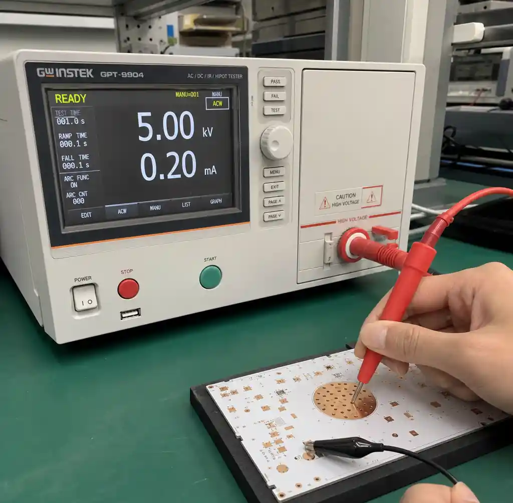
For voltages above a few hundred volts, also check creepage and the material’s CTI (comparative tracking index) per IEC 60112. A thicker dielectric buys isolation but costs thermal performance, which is the central tension in high-voltage power MCPCB design.
Heat Sink Integration and Mounting
The MCPCB base only helps if heat leaves it. That means bolting or clamping the board to a heat sink or chassis through a thermal interface material (TIM), such as a gap pad, sil-pad, or thermal grease.
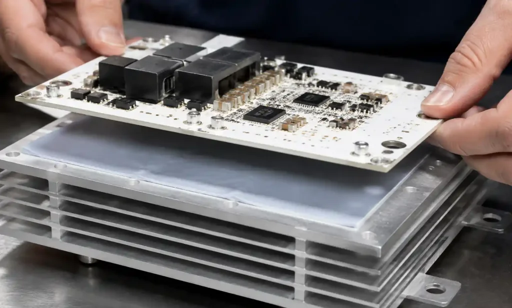
Here is the silent killer: the TIM bond line often dominates total system thermal resistance. A 3 W/m·K gap pad applied too thick can waste the gains from a premium 5 W/m·K dielectric. Minimize bond-line thickness, ensure flatness, and use enough mounting pressure and screws to keep contact even. Plan the mounting-hole pattern and keep-outs during MCPCB panelization so depaneling does not disturb the thermal footprint.
Single vs Double-Sided Construction
Single-sided IMS (insulated metal substrate) gives the shortest, most direct thermal path and the lowest cost. It suits most single-device power stages. Double-sided and thermal-via MCPCBs add routing density, but heat must cross more layers, so thermal performance drops unless you add thermal vias or metal inlays.
| Construction | Thermal path | Best for |
|---|---|---|
| Single-sided IMS | Best, direct | LED, single power stage |
| Double-sided | Moderate | Denser power routing |
| Thermal-via/inlay | Good, complex | Multi-device modules |
Choose the simplest structure that meets your routing needs. Every extra layer between the device and the base metal adds thermal resistance. For validated stackups and finishes, see our MCPCB capability page.
FAQs
What thermal conductivity dielectric do I need for power electronics?
Match it to heat flux. Standard 1–2 W/m·K works for LED and light loads; motor drives and converters want 2–4 W/m·K; SiC and GaN designs benefit from 4–9 W/m·K grades.
Can MCPCB handle wide-bandgap devices like SiC and GaN?
Yes, and it is increasingly the reason to use one. SiC and GaN run junction temperatures above 175°C, so a high-conductivity dielectric and copper base help extract that heat reliably.
Is aluminum or copper base better for high current?
Aluminum handles most high-current designs at lower cost and weight. Choose copper only for extreme heat flux or when routing current through the base itself.
Does MCPCB carry more current than FR4?
Yes. The metal base spreads heat, so for the same temperature rise an MCPCB trace carries more current than the identical FR4 trace. IPC-2152 estimates are conservative for MCPCB.
What standards apply to power MCPCBs?
UL 796 for board safety, UL 94V-0 for flammability, and IPC-6012 for qualification. High-voltage work adds IEC 60112 CTI and creepage checks.
Conclusion
Designing MCPCB for high-current power comes down to four linked choices: base metal, dielectric conductivity, copper weight, and heat-sink coupling. The dielectric and the TIM bond line, not the metal base, usually decide your junction temperature, so specify them from your thermal budget first and confirm isolation second. Get those right and the board becomes an active part of your cooling strategy rather than the weakest link.
Andwin Circuits manufactures aluminum and copper-based MCPCBs with dielectric options from 1 to 8 W/m·K, heavy copper up to 10 oz, and UL-certified, IPC-compliant processes, with fast delivery in 7 days. Contact us today for high-current MCPCB solutions and factory-direct pricing.