
Metal Core PCB Material Selection: Aluminum vs Copper Base
When thermal management becomes critical in high-power LED, automotive power electronics, or industrial motor drives, standard FR-4 boards hit their thermal limit. Metal Core PCBs (MCPCBs) can dissipate heat 8-10 times faster than conventional substrates. However, choosing between aluminum and copper base substrates impacts thermal performance, cost, fabrication complexity, and long-term reliability. This guide provides thermal conductivity data, CTE matching analysis, and application-specific selection criteria for hardware engineers designing power electronics.
What is Metal Core PCB?
Metal Core PCB (MCPCB) is a circuit board technology that uses a metal substrate—typically aluminum or copper—as the base material instead of traditional FR-4. The metal core provides superior thermal conductivity, enabling efficient heat dissipation from high-power components to external heat sinks or chassis. An MCPCB consists of three layers: a copper circuit layer for electrical connections, a thermally conductive dielectric layer for electrical isolation, and a metal base layer for heat spreading.
According to IPC standards, MCPCBs are classified as metal-backed printed boards designed for thermal management applications. The dielectric layer must maintain electrical isolation (breakdown voltage >3kV) while providing thermal conductivity typically ranging from 1-10 W/m·K, depending on the dielectric material formulation.
Aluminum vs Copper Base: Core Material Comparison
Thermal Conductivity Performance
Aluminum MCPCB uses aluminum alloy substrates (typically 5052 or 6061) with thermal conductivity of 138-238 W/m·K. When combined with thermally conductive dielectric layers, the effective system thermal conductivity ranges from 1-3 W/m·K. This represents a 4-8x improvement over FR-4 (0.3-0.4 W/m·K).
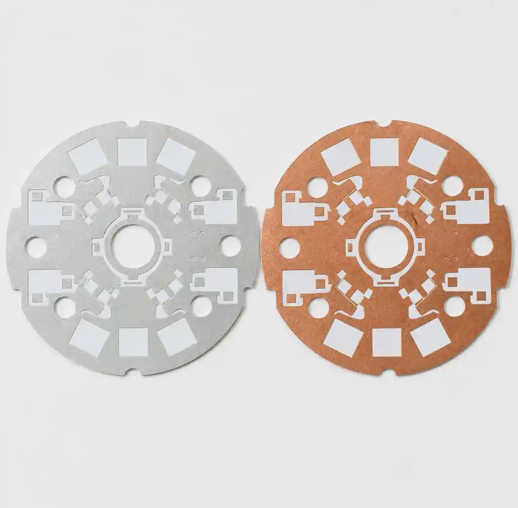
Copper MCPCB employs pure copper substrates with thermal conductivity of approximately 400 W/m·K—nearly double that of aluminum. With advanced dielectric formulations, copper-based systems achieve 8-10 W/m·K effective thermal conductivity. This enables copper MCPCBs to handle power densities exceeding 15W per component, where aluminum-based solutions would overheat.
Material Properties Comparison
| Property | Aluminum MCPCB | Copper MCPCB | Standard FR-4 |
|---|---|---|---|
| Thermal Conductivity | 138-238 W/m·K (base) | ~400 W/m·K (base) | 0.3-0.4 W/m·K |
| System Thermal Conductivity | 1-3 W/m·K | 8-10 W/m·K | 0.3-0.4 W/m·K |
| CTE | 23-24 ppm/°C | 17 ppm/°C | 14-17 ppm/°C |
| Density | 2.7 g/cm³ | 8.9 g/cm³ | 1.85 g/cm³ |
| Cost Relative | 1× (baseline) | 3-5× | 0.3× |
| Machinability | Excellent | Good | Excellent |
CTE Matching Considerations
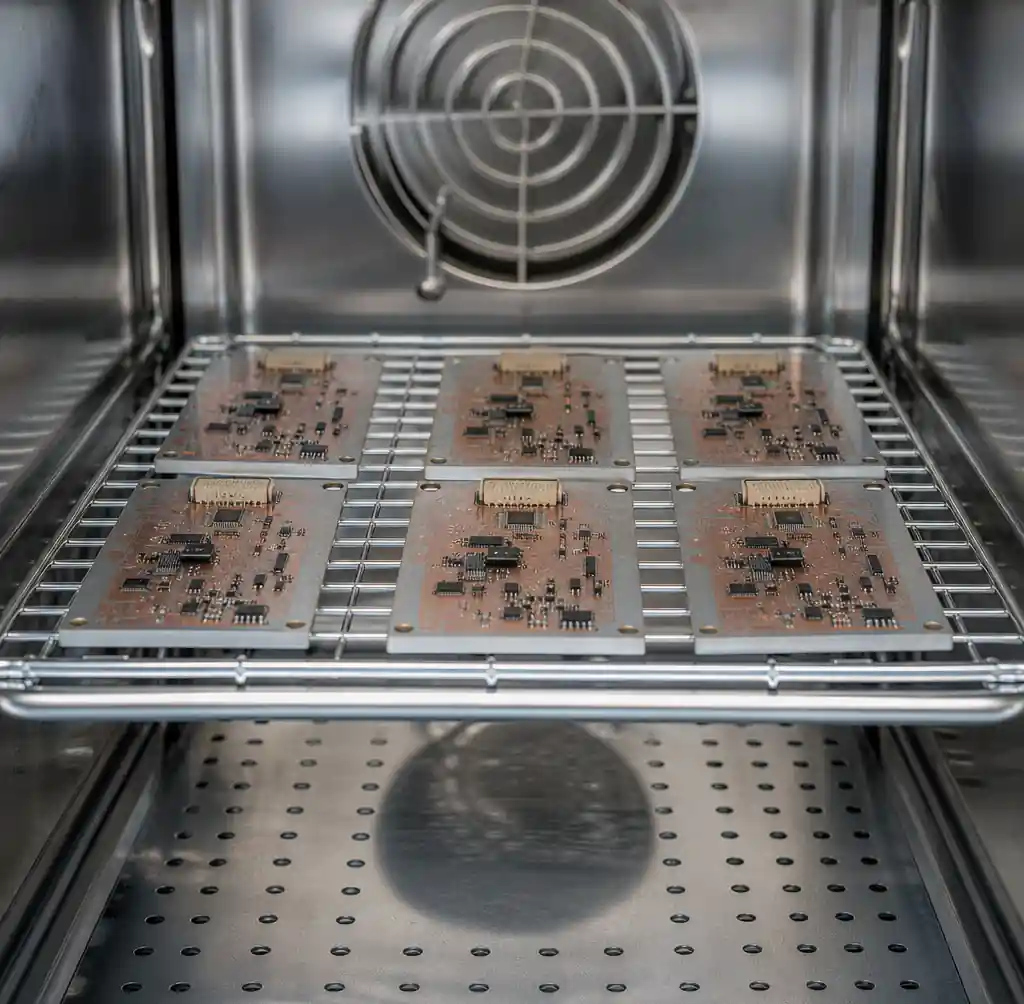
CTE mismatch between substrate and copper traces causes thermal stress during temperature cycling, potentially leading to copper delamination or solder joint fatigue. Copper MCPCB exhibits CTE of 17 ppm/°C, closely matching copper foil (17 ppm/°C), which minimizes thermal stress accumulation. This makes copper base preferred for automotive applications requiring AEC-Q100 qualification with 1000+ thermal cycles from -40°C to +150°C.
Aluminum MCPCB has CTE of 23-24 ppm/°C, creating moderate mismatch with copper traces. For industrial applications with limited thermal cycling (500 cycles or fewer), this mismatch remains acceptable when using appropriate dielectric formulations. You should specify copper base for automotive, aerospace, or any application exceeding 1000 temperature cycles.
Dielectric Layer Selection
Thermal Conductivity Options
The dielectric layer determines overall MCPCB thermal performance while maintaining electrical isolation. Standard dielectric options include:
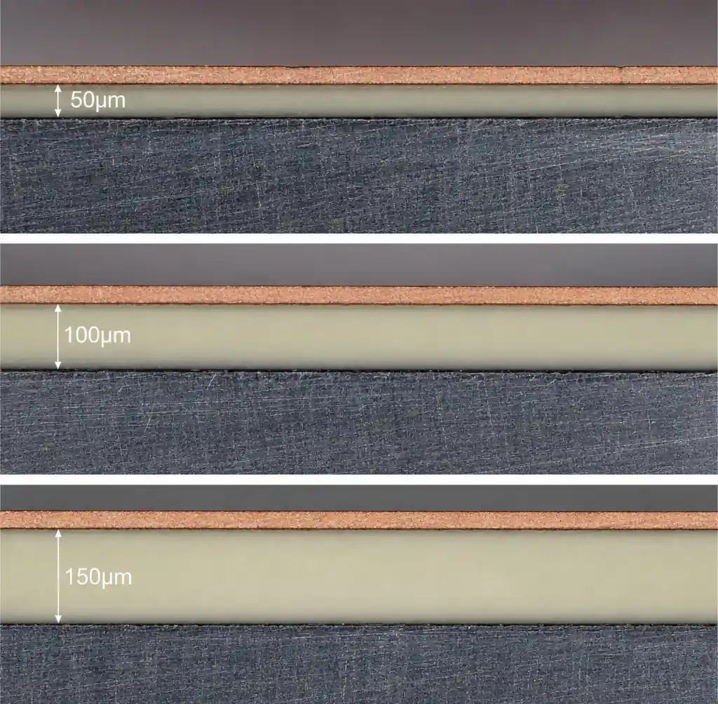
Standard Grade (1.0-1.5 W/m·K): Epoxy-based dielectric suitable for general LED lighting with power densities below 3W per LED. Provides breakdown voltage >2kV at 100μm thickness.
Mid-Grade (2.0-3.0 W/m·K): Ceramic-filled epoxy formulations for high-power LED arrays and automotive lighting. Achieves breakdown voltage >3kV with thermal resistance <0.13°C·in²/W at 100μm thickness. Recommended for 3-8W per component applications.
High-Performance (>3.0 W/m·K): Advanced thermal polymer or ceramic-based dielectrics for extreme power applications. Used in EV charging modules, power inverters, and telecom base stations. Can achieve >5kV breakdown voltage at 75μm thickness.
Dielectric Thickness Trade-offs
| Thickness | Breakdown Voltage | Thermal Resistance | Application |
|---|---|---|---|
| 50-75 μm | 2-3 kV | Low | High thermal, low voltage |
| 100-125 μm | 3-4 kV | Medium | Balanced performance |
| 150-200 μm | >5 kV | High | High voltage isolation |
Thinner dielectrics improve thermal conductivity but reduce breakdown voltage. For high-voltage applications (>400V), you need 150μm+ dielectric thickness to ensure electrical safety per IPC-2221 spacing requirements.
Application-Specific Selection Guide
LED Lighting Applications
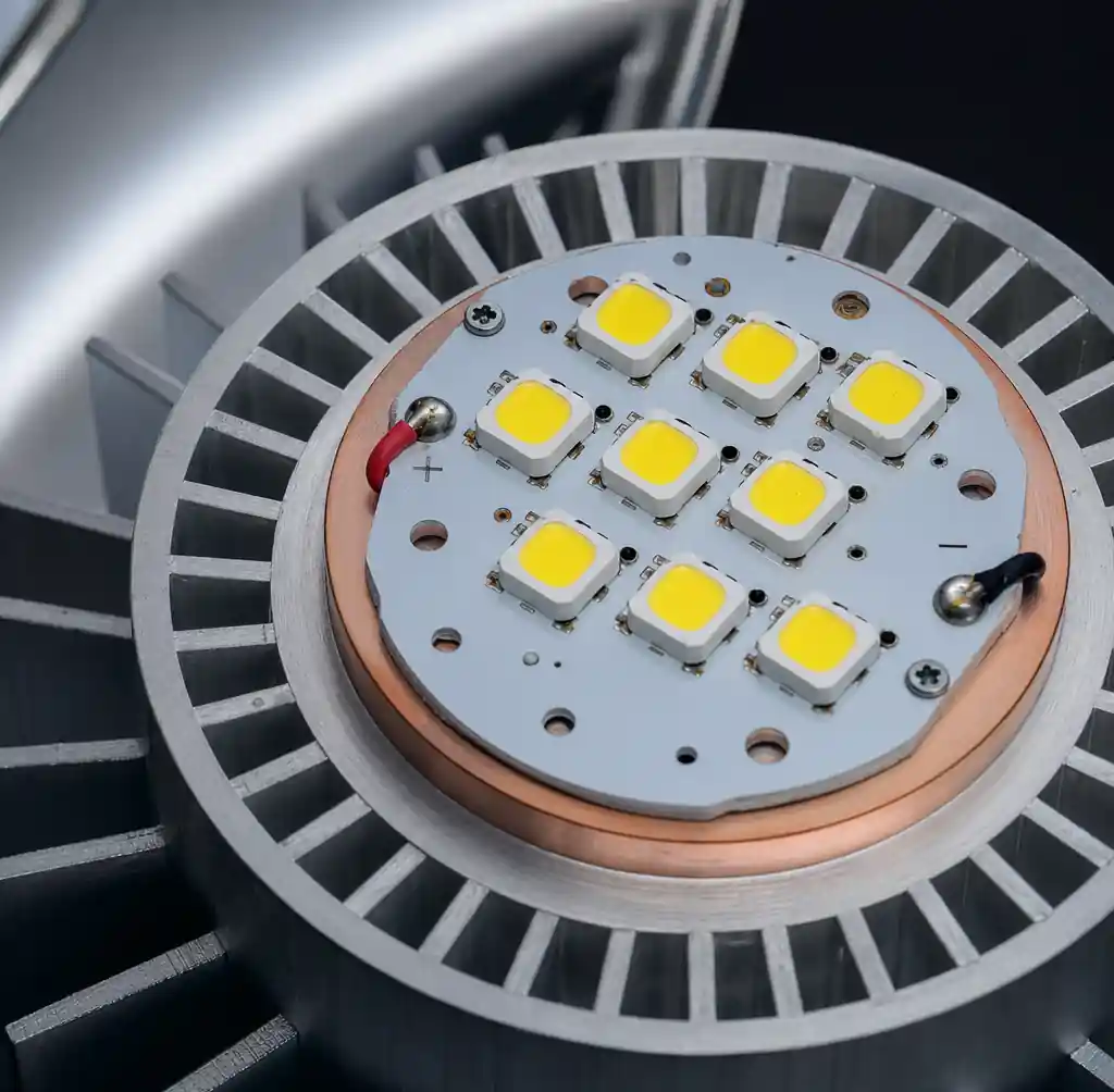
Residential/Commercial LED (0.5-2W per LED):
- Recommended: Aluminum MCPCB with 1.5 W/m·K dielectric
- Base thickness: 1.0-1.5mm
- Why: Cost-effective thermal management for moderate power levels
High-Power LED Arrays (3-8W per LED):
- Recommended: Aluminum MCPCB with 2.5-3.0 W/m·K dielectric
- Base thickness: 1.5-2.0mm
- Why: Mid-grade dielectric provides sufficient heat spreading
Ultra-High-Power LED (>10W per LED):
- Recommended: Copper MCPCB with >3.0 W/m·K dielectric
- Base thickness: 2.0-3.0mm
- Why: Superior thermal conductivity prevents junction temperature rise
Power Electronics Applications
DC-DC Converters (<200W):
- Recommended: Aluminum MCPCB with 2.0 W/m·K dielectric
- Configuration: Single-sided copper, 2oz copper weight
- Design note: Place power MOSFETs and diodes on metal core side
Motor Drives and Inverters (200-1000W):
- Recommended: Copper MCPCB with 3.0+ W/m·K dielectric
- Configuration: Heavy copper (3-4oz) for current carrying
- Critical: CTE matching required for -40°C to +125°C operation
EV Charging Modules (>3kW):
- Recommended: Copper MCPCB with high-voltage dielectric (150-200μm)
- Requirements: >5kV isolation, thermal conductivity >4 W/m·K
- Standards: UL 94V-0, IPC Class 3, automotive qualified
For power electronics design, consider metal core PCB optimization to balance thermal and electrical performance.
Application Decision Matrix
| Application | Power Level | Aluminum MCPCB | Copper MCPCB | Key Factor |
|---|---|---|---|---|
| LED Lighting | <3W per LED | ✓ Optimal | ✗ Overkill | Cost efficiency |
| LED Lighting | 3-8W per LED | ✓ Adequate | ○ Optional | Performance need |
| LED Lighting | >10W per LED | ✗ Insufficient | ✓ Necessary | Junction temp limit |
| Power Electronics | <200W | ✓ Sufficient | ✗ Unnecessary | Standard heat sink |
| Power Electronics | 200-1000W | ○ Marginal | ✓ Preferred | Reliability critical |
| EV/Industrial | >1kW | ✗ Inadequate | ✓ Required | Auto qualification |
Fabrication and Manufacturing Differences
Drilling and Routing
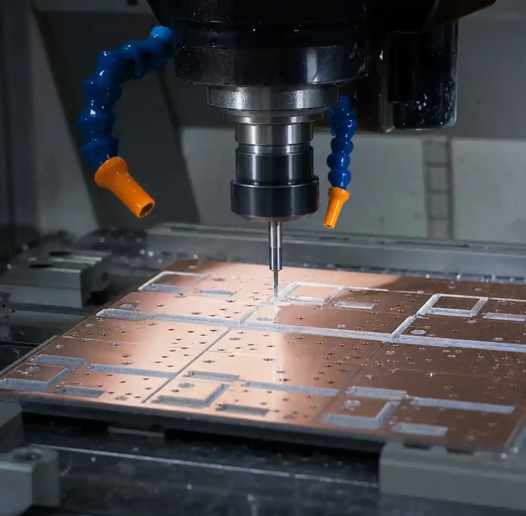
Aluminum MCPCB allows standard carbide drill bits for via drilling. The soft aluminum substrate machines easily without excessive tool wear. CNC routing for board outline uses standard parameters with minimal burr formation.
Copper MCPCB requires specialized drill bits and slower feed rates due to copper’s hardness. Drill bit life decreases by 40-60% compared to aluminum processing. You must use diamond-coated or carbide tools for routing operations. This increases per-board manufacturing cost by 15-25%.
Lamination Process
Aluminum base lamination occurs at 150-180°C with moderate pressure (15-20 kg/cm²). The aluminum substrate’s excellent thermal uniformity ensures consistent dielectric bonding. Lamination cycle time: 60-90 minutes.
Copper base requires higher lamination temperatures (180-200°C) and pressure (20-25 kg/cm²) to achieve proper dielectric adhesion. The higher thermal mass of copper extends heating and cooling cycles by 20-30%.
Cost Analysis and Selection Decision
Material Cost Breakdown
Aluminum MCPCB represents the baseline cost. For a typical 100mm × 150mm single-sided board:
- Aluminum base (1.5mm): $3-5 per board
- Standard dielectric (1.5 W/m·K): $2-3 per board
- Copper circuit layer (2oz): $2-3 per board
- Total material cost: $7-11 per board
Copper MCPCB costs 3-5× more:
- Copper base (2.0mm): $12-18 per board
- High-performance dielectric (3.0+ W/m·K): $5-8 per board
- Copper circuit layer (2-3oz): $3-4 per board
- Total material cost: $20-30 per board
ROI Calculation Factors
When evaluating copper vs aluminum, consider total system cost:
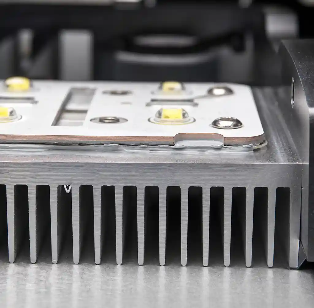
Heat sink savings: Copper MCPCB’s superior thermal performance may allow smaller, cheaper heat sinks, offsetting substrate cost premium. For 50-100W applications, heat sink cost reduction can reach $5-15 per unit.
Reliability benefits: Copper’s CTE matching reduces thermal fatigue failures in automotive/industrial applications. Warranty cost reduction from improved reliability may justify 3-5× substrate cost increase.
You should choose copper MCPCB when thermal performance directly impacts product reliability or when heat sink size/cost becomes prohibitive. For cost-sensitive consumer products with adequate thermal budget, aluminum provides better value.
Design Guidelines and DFM Considerations
Thermal Via Design
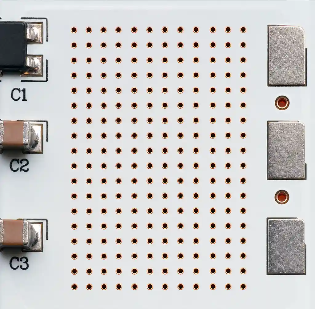
Both aluminum and copper MCPCBs benefit from thermal via arrays connecting component pads directly to the metal core. For maximum heat transfer:
- Use 0.3-0.5mm diameter vias under thermal pads
- Space vias at 1.0-1.5mm pitch in a grid pattern
- Fill vias with thermal epoxy or copper plating
- Ensure dielectric layer has via openings for direct metal contact
Component Placement Strategy
Place high-power components on the metal core side for direct thermal coupling. Maintain minimum 3mm spacing between power components to prevent thermal cross-talk. For two-sided MCPCBs, place lower-power control circuitry on the non-metal side.
Avoid placing temperature-sensitive components (electrolytic capacitors, crystal oscillators) near high-power devices. Route thermal paths from power devices to board edges where heat sinks attach.
For questions about metal core PCB capabilities, consult with your PCB manufacturer during design phase.
Industry Standards and Certifications
IPC Standards Compliance
Both aluminum and copper MCPCBs must meet IPC-6012 Class 2 or Class 3 requirements:
- Class 2: General electronics, consumer products
- Class 3: High reliability (automotive, medical, aerospace)
Key IPC-6012 requirements for MCPCBs:
- Minimum dielectric breakdown voltage: 2.5kV for Class 2, 3.5kV for Class 3
- Thermal stress test: 6 cycles at 288°C (10 seconds each)
- Peel strength: >1.0 N/mm for copper foil adhesion
UL Certification
UL 94V-0 flammability rating is standard for MCPCBs used in safety-critical applications. Both aluminum and copper substrates with appropriate dielectric formulations achieve V-0 rating.
For high-voltage applications (>400V), UL recognition is required for dielectric system. Verify that your MCPCB manufacturer provides UL-certified materials with documented breakdown voltage ratings.
FAQ
Q: Can I use aluminum MCPCB for automotive applications?
A: Yes, for low-to-mid power automotive electronics (<5W per component). For high-power automotive applications requiring AEC-Q100 qualification with extreme temperature cycling, copper MCPCB provides better long-term reliability due to superior CTE matching.
Q: What is the maximum operating temperature for aluminum vs copper MCPCB?
A: Both aluminum and copper substrates handle continuous operating temperatures up to 150°C. The limiting factor is typically the dielectric layer’s glass transition temperature (Tg), ranging from 130-180°C. Copper’s superior thermal conductivity keeps component junction temperatures lower.
Q: How do I calculate thermal resistance for MCPCB design?
A: Total thermal resistance = junction-to-case + interface resistance + dielectric resistance + base spreading resistance + heat sink resistance. Use thermal simulation software for accurate modeling, or request thermal analysis from your MCPCB manufacturer.
Q: Can MCPCBs be used for multilayer designs?
A: Standard MCPCBs are single or double-sided. For multilayer requirements, consider hybrid stackups with metal core embedded between FR-4 layers, or evaluate ceramic PCB alternatives for extreme thermal performance.
Q: What surface finish works best for high-power MCPCB applications?
A: ENIG provides flat surface for fine-pitch components, excellent solderability, and no thickness variation. For wave soldering applications, HASL remains cost-effective. Avoid OSP for high-temperature applications (>150°C) due to limited thermal stability.
Conclusion
Aluminum and copper metal core PCBs address different thermal management requirements. Aluminum MCPCB provides cost-effective thermal performance for LED lighting and mid-power electronics up to 8W per component, while copper MCPCB delivers superior heat dissipation necessary for automotive power electronics, EV charging, and applications exceeding 10W per device. Your selection depends on power density, thermal cycling requirements, and total system cost including heat sink and reliability considerations.
Andwin Circuits manufactures aluminum and copper metal core PCBs with thermal conductivity from 1-8 W/m·K, supporting single and double-sided configurations up to 500×600mm board size. Our facility is certified to ISO 9001, IATF 16949, and UL standards, with metal core PCB capabilities including heavy copper (up to 6oz), high-voltage dielectric (>5kV), and fast turnaround for prototype and production volumes. Contact us for MCPCB design review, thermal analysis, and factory-direct pricing for your thermal management projects.