
PCB Reflow Profile: Temperature Curves for Lead-Free Assembly
When transitioning to RoHS-compliant manufacturing, understanding lead-free reflow profiles isn’t optional—it’s the difference between reliable solder joints and field failures. At Andwin Circuits, we’ve profiled thousands of assemblies using SAC305 solder, and proper temperature curves reduce defects by 40% compared to generic profiles copied from paste datasheets.
Why Lead-Free Reflow Profiling Demands Precision
Lead-free solder alloys, primarily SAC305 (Sn96.5/Ag3.0/Cu0.5), melt at 217°C—34°C higher than eutectic tin-lead. This elevated temperature compresses your process window, increases thermal stress on components, and demands tighter control over every reflow phase.
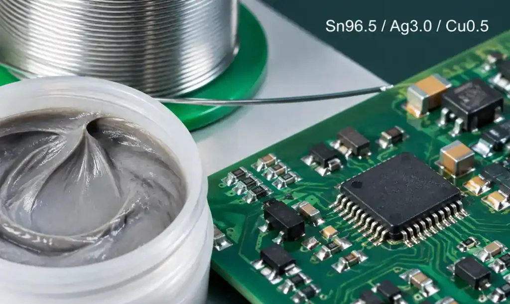
The challenge isn’t reaching peak temperature. It’s managing thermal gradients across components with different thermal masses while staying within tolerance envelopes. A 0402 resistor and large BGA don’t heat at the same rate, yet both require proper intermetallic formation without overheating.
The Four Critical Zones of Lead-Free Reflow
Preheat Zone: Controlled Thermal Ramp
Ramp rates between 1-3°C per second bring assemblies to approximately 150°C. Too fast risks thermal shock on ceramic capacitors and large components. Too slow extends process time unnecessarily, affecting throughput.
This zone activates flux chemistry and drives off volatile solvents. Components begin equalizing thermally, reducing delta-T that causes warpage. For boards with mixed component densities, slower ramp rates (1-1.5°C/s) provide better equalization.
Soak Zone: Thermal Equilibration
The soak zone operates between 150-200°C for 60-120 seconds, though IPC-7530A permits ranges up to 221°C depending on paste chemistry. This phase minimizes temperature differentials across the assembly before reflow begins.
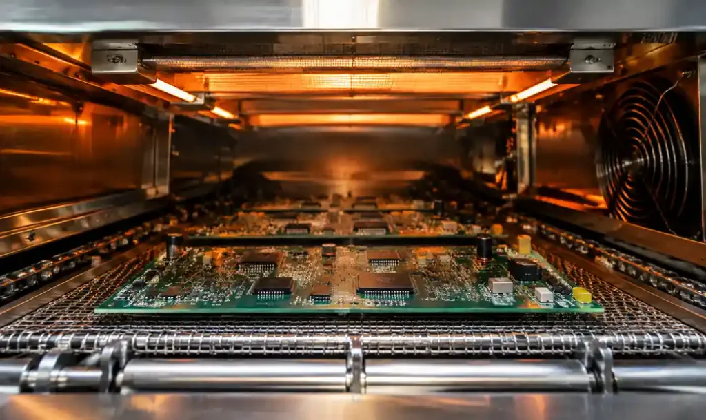
Flux activation occurs here, removing oxides from pad surfaces and component terminations. Insufficient soak time leaves temperature gradients causing incomplete reflow or tombstoning. Excessive time degrades flux activity before solder melts, reducing wetting performance.
Reflow Zone: Above Liquidus
Solder transitions from paste to metallurgical joint here. SAC305’s liquidus temperature of 217°C marks the critical threshold. Time above liquidus (TAL) should be 45-90 seconds—enough for complete melting and intermetallic formation without excessive growth or component damage.
Peak temperatures range from 235-250°C measured at the board. Component datasheets specify maximum body temperatures; exceeding these risks delamination, package cracking, or die attach degradation. For moisture-sensitive devices, even brief excursions beyond rated limits cause popcorning.
Peak shape matters. Sharp spikes create thermal stress. Rounded peaks with 20-40 seconds near maximum temperature provide better joint formation while managing component stress, measured as Process Window Index (PWI).
Cooling Zone: Grain Structure Formation
Controlled cooling solidifies joints and establishes grain structure. Most profiles target 2-4°C per second until solder solidifies below 200°C, then allow natural convection cooling.
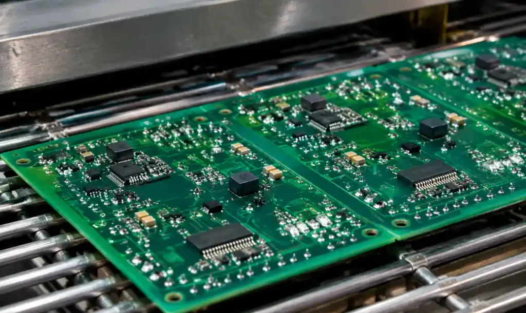
Inconsistent cooling causes warpage, particularly in large boards or assemblies with metal stiffeners. If post-reflow inspection shows components shifted from pad centers, examine cooling uniformity.
Lead-Free vs. Leaded Comparison
| Parameter | SAC305 (Lead-Free) | SnPb (Leaded) | Impact |
|---|---|---|---|
| Liquidus Temperature | 217°C | 183°C | 34°C higher process temperature |
| Peak Temperature Range | 235-250°C | 210-230°C | Narrower margin to component limits |
| Time Above Liquidus | 60-90 seconds | 45-75 seconds | Extended thermal exposure |
| Process Window | Tighter | Wider | Requires precise oven tuning |
The comparison reveals why simple temperature increases fail. Longer time above liquidus, combined with elevated peaks, means components experience more thermal stress. Parts rated for 260°C in leaded processes may fail in lead-free assembly without controlled TAL.
Critical Process Parameters to Monitor
Time Above Liquidus (TAL)
TAL measures solder’s molten duration. Below 45 seconds risks incomplete intermetallic formation—joints that look acceptable but fail under thermal cycling. Beyond 90 seconds, excessive intermetallic growth creates brittle joints and damages heat-sensitive components.
Peak Temperature (PT)
Peak temperature must exceed solder liquidus by 20-35°C for reliable wetting but stay below component limits. For SAC305, target 240-245°C at the board. BGAs and QFNs with large thermal masses may read 5-10°C lower than exposed small components on the same board.
Soak Time (ST)
Proper soak duration (60-120 seconds) correlates directly with defect rates. Assemblies with insufficient soak show three times more non-wets and cold joints than properly soaked boards, allowing temperature equilibration across components.
Component-Specific Considerations
Moisture-Sensitive Devices (MSDs)
Moisture Sensitivity Level (MSL) ratings define baking and floor life before reflow. During reflow, internal moisture vaporizes, creating pressure that cracks packages (popcorning) or delaminates die attach.
| MSL Rating | Floor Life (≤30°C/60%RH) | Bake Requirement |
|---|---|---|
| MSL-1 | Unlimited | Never required |
| MSL-2 | 1 year | After expiration |
| MSL-3 | 168 hours (7 days) | After >168 hour exposure |
| MSL-4 | 72 hours (3 days) | After >72 hour exposure |
| MSL-5 | 48 hours (2 days) | After >48 hour exposure |
| MSL-6 | Immediate | Mandatory before use |
Baking at 125°C for 24 hours drives out absorbed moisture. High-volume production benefits from dry storage cabinets (<5% RH) eliminating most bake cycles.
BGAs and Large Packages
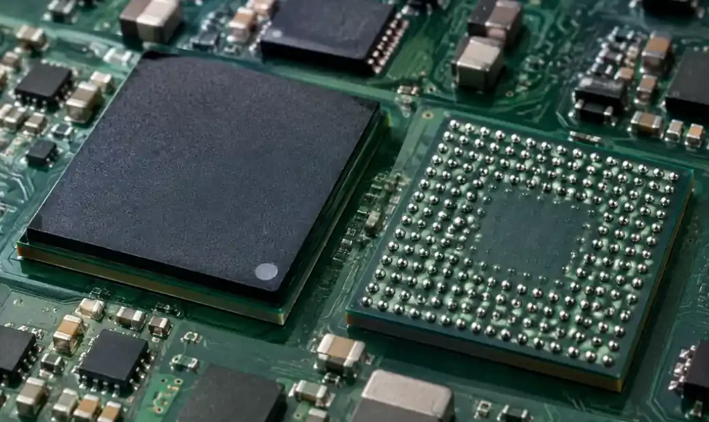
Ball grid arrays create profiling challenges. Package mass acts as a heat sink, creating lag between board and die temperature. Most BGA datasheets specify temperature measured at package center, requiring prediction or direct measurement. Board-level thermocouples placed adjacent to BGAs provide indirect monitoring, typically reading 5-15°C higher than actual package body.
LEDs and Optical Components
LED phosphor coatings degrade above 245°C, causing color shift or reduced output. Most LED manufacturers specify 250-260°C maximum with TAL reduced to 45-60 seconds. For boards mixing standard components and sensitive LEDs, optimize profiles for LEDs or use selective reflow with LEDs on the secondary side for a lower-temperature second pass.
Thermocouple Placement for Accurate Profiling
Temperature measurement accuracy determines profile validity. Attach thermocouples with high-temperature solder or adhesive—not kapton tape alone, which creates insulation skewing readings. Profile at these locations:
- Largest thermal mass component (typically BGA or shield)
- Smallest passive (usually 0402 resistor or capacitor)
- Temperature-sensitive component (connector, LED, or lowest-rated device)
- Board center and edges checking uniformity
Run three boards minimum to establish repeatability. Thermal variation between boards indicates oven zoning issues or conveyor problems affecting heat transfer uniformity.
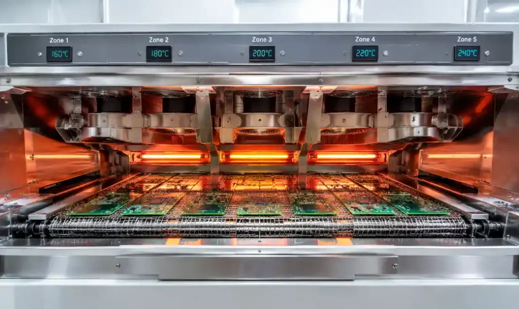
Oven Configuration and Profile Optimization
Most production reflow ovens have 6-12 heating zones. Proper profiling balances zone setpoints to create the desired board temperature curve. Oven internal temperature doesn’t directly correlate to board temperature—convection efficiency, belt speed, and board thermal mass affect heat transfer.
Start with manufacturer-recommended zone temperatures for your belt speed. After profiling, adjust zones incrementally (5-10°C) to modify curve segments. Belt speed determines zone residence time. Faster speeds increase throughput but compress timelines for thermal processes. Boards moving at 100 cm/min spend less time in zones than at 50 cm/min, requiring higher zone temperatures for the same curve.
Common Defects Linked to Profile Issues
Poor profiles create predictable defect signatures. Non-wets and insufficient solder on large components indicate inadequate soak time or low peak temperature. Tombstoning and component shift indicate rapid preheat heating or uneven zone temperatures creating thermal gradients.
Solder balling appears when flux degrades before reflow from excessive soak temperature or prolonged time above 180-190°C. Flux loses activity, oxide removal stops, and solder balls rather than wetting.
Component damage—cracked packages, lifted bond wires, or delamination—points to excessive peak temperature or TAL. Cross-reference component datasheets. If rated maximum is 260°C and profile peaks at 248°C, examine TAL duration. Prolonged exposure causes damage below absolute limits.
Profile Validation and Process Control
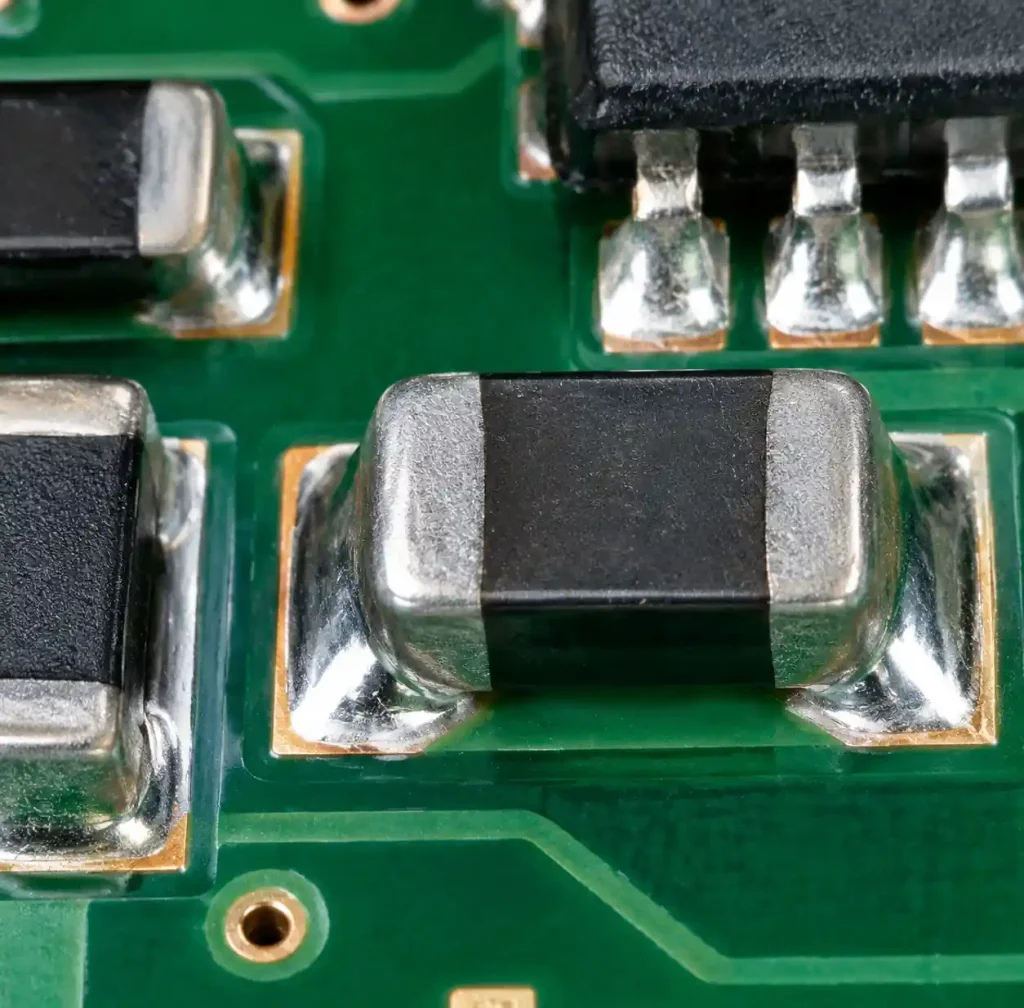
Profile validation requires reliability testing. Thermal cycling (-40 to +125°C) for 1000 cycles reveals whether joints formed properly. Boards passing visual and X-ray inspection can fail early in service if intermetallic formation was incomplete.
For high-reliability applications (automotive, medical, aerospace), document every profile parameter and establish statistical process control. Monitor TAL, peak temperature, and soak time on every production run. Trend analysis reveals oven degradation or zone heater failures before creating scrap.
IPC-7530A provides guidelines for temperature profiling in mass soldering. While not prescriptive, it establishes measurement methods and critical parameter ranges. Major semiconductor manufacturers (Texas Instruments, NXP, Microchip, Renesas) publish reflow recommendations specific to their packages that override generic guidelines.
FAQ
Q: Can I use the same reflow profile for all SAC305 pastes?
No. Different paste formulations have specific flux chemistry and powder characteristics affecting optimal soak temperature and time. Start with paste supplier recommended profiles, then adjust based on assembly thermal behavior and component requirements.
Q: How often should I re-validate my reflow profile?
Re-profile when changing solder paste, significantly modifying board design (layer count, copper weight, size), switching component suppliers for thermally critical parts, or after oven maintenance affecting heating elements. Quarterly verification on stable processes catches gradual oven degradation.
Q: What’s the difference between component body and board temperature?
Board temperature measures PCB surface with thermocouples on pads or traces. Component body temperature measures the package itself. Large components heat slower than boards due to thermal mass. Datasheets specify maximum body temperature—estimate or measure package temperature, not just board temperature.
Q: Why do sources show different peak temperatures (240°C vs. 250°C vs. 260°C)?
Peak temperature recommendations vary based on component limitations, not solder requirements. SAC305 works metallurgically across wide ranges. The constraint is component damage threshold. Match peak to your most sensitive component while exceeding liquidus by 20-30°C.
Q: How do I handle boards with very high component density or mixed thermal masses?
High-density boards require careful thermocouple placement and potentially slower belt speeds for better thermal equalization. Profile the most thermally sensitive component, then validate others reach minimum requirements. In extreme cases, selective soldering or two-stage reflow (different temperatures for top/bottom) solves impossible thermal conflicts.
Q: What causes the slope between soak and reflow zones to matter?
Ramp rate from soak to peak affects flux activity and thermal stress. Too steep (>3°C/s) risks shocking components while flux hasn’t fully activated. Too shallow (<0.5°C/s) degrades flux during prolonged heating, reducing wetting. Target 1-2°C/s balancing thermal stress with active flux.
Conclusion
Lead-free reflow profiling demands precision generic curves cannot provide. Your profile must balance SAC305’s 217°C liquidus against component thermal limits, managing time above liquidus, peak temperature, and soak duration to form reliable joints without damage. Validated profiles differ from copied curves in field reliability—properly formed intermetallics survive thermal cycling and mechanical stress.
Profile development isn’t one-time work. Board revisions, component changes, paste variations, and oven aging require revalidation. Measure critical parameters continuously, establish statistical controls, and maintain documentation. At Andwin Circuits, we treat every profile as assembly-specific, because in lead-free reflow, precision isn’t perfectionism—it’s production necessity.