Rigid Flex PCB Design
PCB material stock quick delivery!
Rigid Flex PCB Design Guidelines
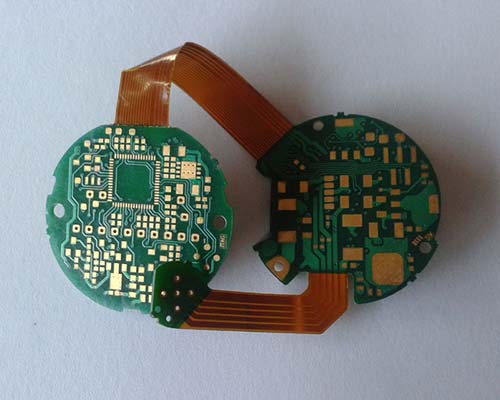
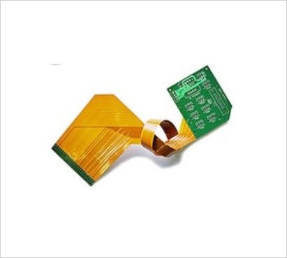
Broadly speaking, a rigid flex PCB design will closely resemble a hardboard design, with the flexible layers fully extending into the rigid areas of the board. Similarly to hardboard layouts, a rigid flex PCB fabrication package will include Gerber layers, along with drill files, solder mask layers, nomenclature, perimeter/rout files, coverlayer, etc.
However, there are some key differences between the fabrication packages for rigid flex PCB’s and hardboard applications:
- A rigid flex PCB generally has many more dimensions on it, and should carefully define the requirements, as these boards are generally used in 3D applications. It should also accurately define the rigid to flex transition areas, as these are not always apparent when viewing the Gerber layers alone.
- The material layup in rigid flex boards is critical, and should be worked out in collaboration with fabricator. We can help you make the right choices in materials based your requirements such as UL flammability rating, minimum bend radii required, mechanical considerations, impedance control on both flex and rigid layers, RoHS certification, lead free assembly compatibility, and other considerations.
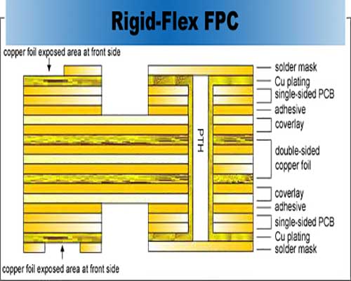
- Rigid flex PCB boards usually require additional layers in the Gerber files. Layers 1 and X will have solder mask layers, but you will also need artwork layers that define the coverlayer and bondply sections (if required) of the board, and how much each go into the hardboards. IPC 2223 recommends 0.100″ but fabricator may be able to accommodate less than that.
The IPC-2223 Sectional Design Standard for Flexible Printed Boards is an excellent resource for wise practices in both flexible circuit and rigid flex circuit design.

Layout guidelines
- Make track-width and –spacing within the flexible part as wide as possible
- At best, the transitions from wide to narrow tracks are continually rejuvenated
- Rasterize ground planes(as recommended also for rigid printed circuit boards)
- From 2 flex layers, shifted placement of tracks on the PCB top and bottom
- Make soldering surfaces and annular rings as large as possible
- Make connections of tracks and solder pads in a tear-drop, rounded style
- Stiffeners (partial mechanical reinforcements, for example, in the plug-in or mounting area) can achieve final thicknesses of 0.2 mm – 1 m

Pads and Vias on flexible PCBs
In general, the copper adhesion in flexible circuit boards is worse than in circuit boards with standard FR4 material. It is therefore recommended to make the pads / annular rings as large as possible. To improve adhesion, anchors and teardrops can be used.
In order to increase the stability of vias on flexible circuit boards, you can implement the following measures:
- Give anular rings the maximum size
- Bind vias using teardrops
- Use anchors to increase the film adhesion
- Do not place any vias in the bending area

RIGID-FLEX VS. RIGID PRINTED CIRCUIT BOARD DESIGN
If you know your new product will need to partially bend, flex, or fold, you’ll likely need to use flex circuits and/or rigid-flex boards for your new product. Most present-day designs require several signal layers within your rigid PCB, and using a rigid-flex board will still allow you to use multiple signal layers while complying with your mechanical requirements.
The additional design considerations for flex circuits and rigid-flex circuits may include board materials, vias, and thermal management, which can test the limits of some PCB design programs. However, with Altium Designer, designing rigid-flex boards is easy.
- Making the right design choices requires weighing the trade-offs between flex and rigid-flex PCB design. If you’re working on the latest and greatest IoT and wearables, it pays to know when to use each type of PCB.
- Rigid-flex and flex PCBs have been around for some time, but flex PCBs are set to be the wave of the future, especially in wearable devices.
- Not all designers or engineers are familiar with flex and rigid-flex design, but the right design software and techniques will help you be successful.

Reasons to Choose Rigid Flex PCB
Traditional rigid-flex PCB designs allowed you to mount components, connectors, and the chassis for your product to the physically stronger rigid part of the assembly. Again, in terms of traditional designs, the flexible circuit only served as an interconnect while lowering the mass and improving the resistance to vibration.
About Andwin Circuits
Andwin Circuits as a industry leading of PCB manufacturer since 2003.
Specializing in multilayer PCB, Rigid flex PCB, HDI PCB, controlled impedance PCB and Radio Frequency circuit, from quick turn prototype to mass products.
