
Selective Soldering: When to Use It Instead of Wave Soldering
For PCB manufacturers and engineers designing mixed-technology assemblies, the choice between selective soldering and wave soldering is critical—it affects quality, cost, and production efficiency. Yet many teams default to one process without fully understanding when each excels. This guide cuts through that confusion with practical decision frameworks and real-world scenarios.
The Core Difference: One Process, Two Worlds
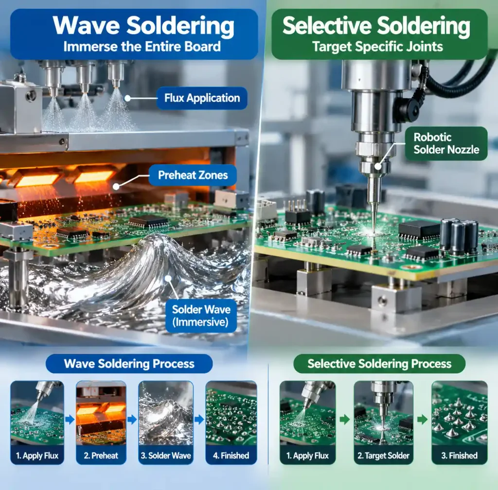
Wave soldering immerses the entire board into molten solder, exposing all through-hole components to high temperatures simultaneously. This works beautifully for boards dominated by through-hole parts, where the thermal stress on SMT components is minimal.
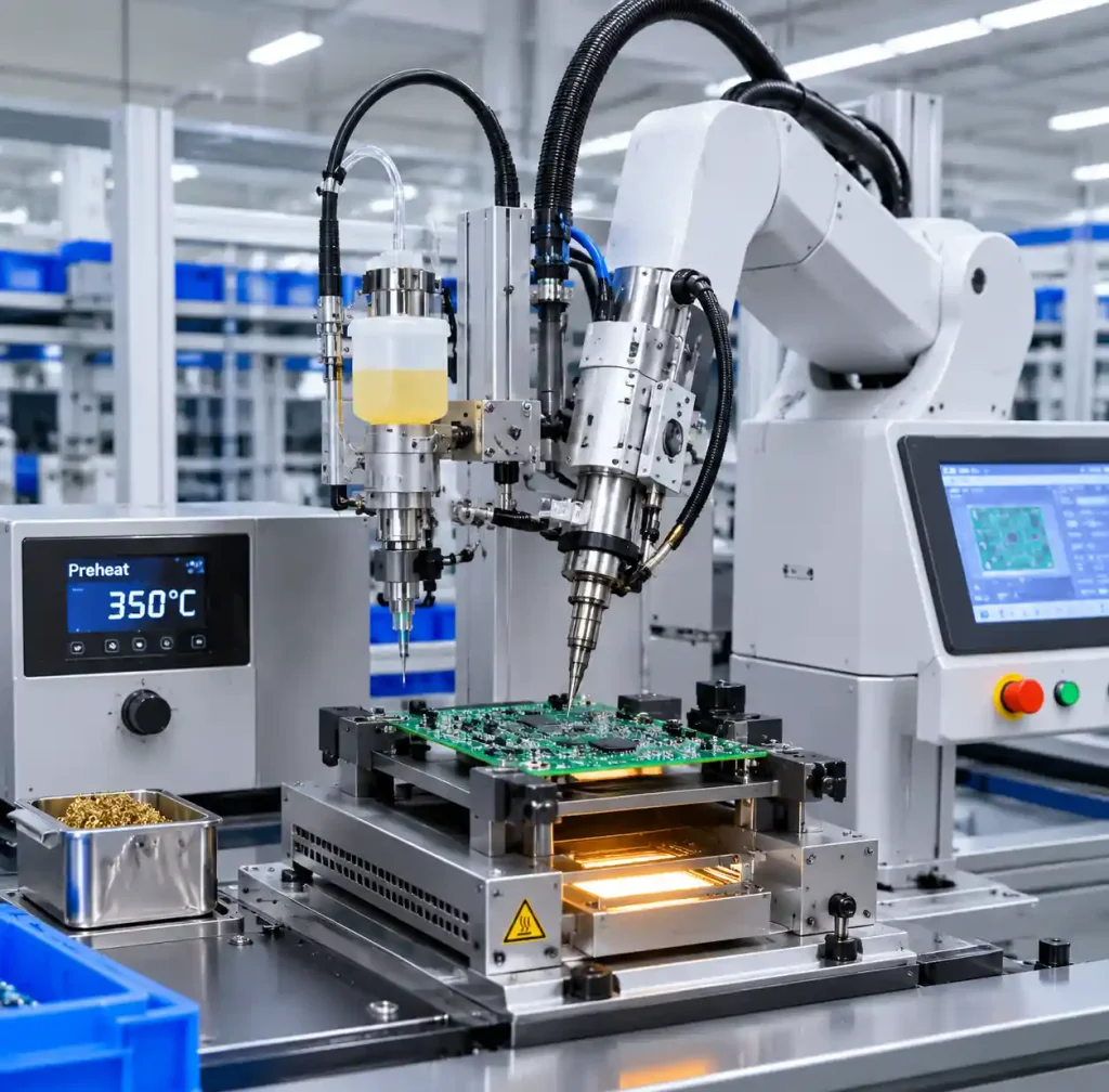
Selective soldering targets specific through-hole joints with programmed robotic nozzles, leaving the rest of the board undisturbed. A flux applicator, preheater, and solder pump work in precise sequence—flux is applied to selected joints, the board is preheated, and the nozzle delivers solder to each target area individually.
The distinction seems technical, but the implications are profound. Wave soldering is thermal sledgehammer; selective soldering is a precision scalpel. Understanding when you need which one determines whether your board emerges pristine or damaged.
When Wave Soldering Still Wins
High-volume production of simple through-hole designs. Wave soldering excels when you’re producing 10,000+ units annually with minimal SMT content—connectors, THT resistors, and axial capacitors dominating the underside. The speed is unmatched: a modern wave machine processes 40–60 boards per minute. Selective soldering, by contrast, runs at 5–15 boards per minute, depending on joint count and complexity.
Cost per unit at scale. For pure through-hole assemblies, wave soldering’s setup is straightforward and inexpensive. Selective soldering requires detailed CAD data, nozzle tooling design, and program optimization. Below roughly 5,000 annual units of the same design, selective soldering’s cost-per-part advantage erodes.
Consistent solder fillets. Wave soldering produces predictable fillet geometries because solder bridges every joint simultaneously. The thermal mass, angle, and contact are uniform across the board. Many legacy industrial equipment specifies wave soldering precisely because fillet consistency is proven and documented.
Why Selective Soldering Is Essential for Mixed-Tech Boards
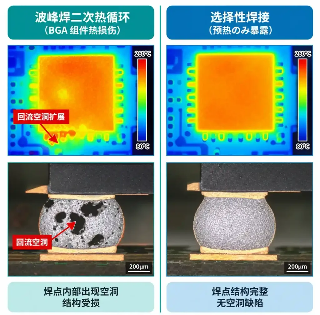
Thermal protection for heat-sensitive SMT components. This is selective soldering’s killer application. Imagine a board with 100 SMT parts already reflowed at 245°C, now with 20 THT connectors that need soldering. Passing the entire assembly through a 260°C wave exposes those SMT parts to a second thermal cycle, risking:
- Solder joint cracking from CTE mismatch
- Package delamination in moisture-sensitive devices
- Intermetallic growth in lead-free solder joints
- Ball-grid-array (BGA) reflow voids expanding further
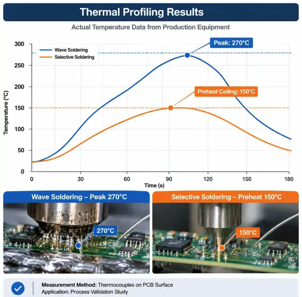
With selective soldering, SMT components see only 120–150°C preheat—enough to activate flux and enable good wetting, but far below their reflow temperature. No second thermal shock. No rework required.
Protection of precision circuits. Test boards, IC sockets, and connectors near high-speed signal traces benefit enormously. Wave soldering produces flux spray-back and aerosol that coats nearby components and traces—within 8mm of solder entry, flux contamination is routine. This contamination causes:
- Creeping leakage currents between signals and ground
- Intermittent shorts under thermal or humidity stress
- Reliability failures in field diagnostics (>10ppm defect rates reported)
Selective soldering’s localized approach eliminates spray-back entirely.
Handling complex board geometry. When connectors, test points, or large through-holes are unevenly distributed, or components stick through the board at different heights, wave soldering struggles. Selective soldering simply programs each joint individually—no mechanical shielding pallets required, no design compromises.
Detailed Comparison: Decision Matrix
| Factor | Wave Soldering | Selective Soldering |
|---|---|---|
| Throughput (boards/min) | 40–60 | 5–15 |
| Cost per unit (5k+ annually) | $0.15–$0.35 | $0.40–$0.80 |
| Cost per unit (100–500 units) | $1.50–$3.00 | $0.80–$1.50 |
| Thermal exposure (peak, °C) | 260–280 | 150–180 |
| SMT component risk | High (2nd thermal cycle) | Minimal (preheat only) |
| Setup time | 15–30 min | 2–4 hours (includes CAD, tooling) |
| Solder joint consistency | Excellent (uniform geometry) | Very good (program-dependent) |
| Rework flexibility | Limited (wave must be repeated) | High (individual joints can be re-soldered) |
| Lead time | 1–3 days | 3–7 days (CAD/tooling) |
| BGA/dense SMT protection | Poor | Excellent |
Real-World Scenarios: When to Choose Each
Scenario 1: Consumer IoT Gateway (Selective Soldering)
Board composition: 150 SMT components (0402–LQFP144), 8 USB connectors, 2 power jack sockets.
Wave soldering would subject BGA memory devices to >260°C twice. Selective soldering’s preheat keeps components cool while soldering the connectors safely. Expected result: first-pass yield >98% vs. 92% with wave soldering and rework.
Scenario 2: Industrial Power Supply (Wave Soldering)
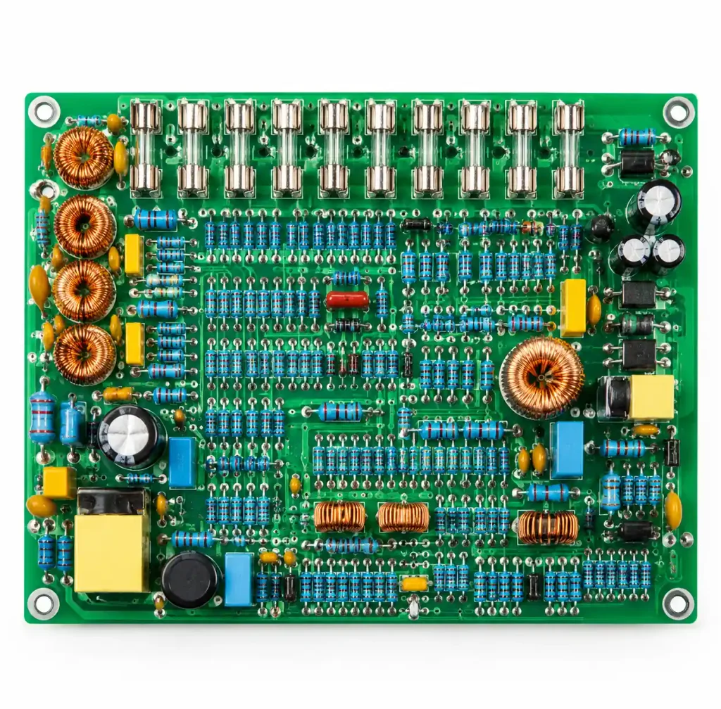
Board composition: 300 through-hole resistors, 40 power inductors, 12 fuses, no SMT below the wave line.
This is wave soldering’s domain. Pure through-hole production in high volume—40+ units per minute flow through the machine. Selective soldering would be overkill cost-wise, and wave soldering’s proven fillet geometry ensures compliance with IEC 61010 safety standards. First-pass yield: 99.2%.
Scenario 3: Medical Device with Mixed Assembly (Selective Soldering)
Board composition: 60 SMT components, Class 3 assembly, 4 precision connectors, IPC-6012 Class 3 compliance required.
Selective soldering is mandatory here. The second thermal cycle from wave soldering could crack solder joints on BGA components—a critical failure in Class 3 assembly. IPC-6012 Class 3 also mandates exceptional fillet quality and void-free joints, which selective soldering delivers with minimal rework (selective soldering rework rate: ~0.5% vs. wave at 2–3% for mixed boards).
Process Quality: The Fine Print
Selective soldering’s hidden complexity. A successful selective solder program depends on:
- CAD accuracy – If through-hole pad coordinates are off by 0.5mm, the nozzle misses, and you get a cold joint or no solder at all. Validate CAD against Gerbers with 100% coordination checking.
- Nozzle thermal control – Solder pot temperature, preheat time, and nozzle dwell time must match your specific board thickness, copper weight, and component mass. A 0603 resistor and a 2mm connector require different thermal profiles.
- Flux chemistry – No-clean flux used in reflow can interact poorly with selective solder paste. No-clean flux on SMT → OA/RMA flux on through-hole = potential ionic residue interaction. Use compatible chemistries.
- Board handling – Pallets and fixtures must be precision-machined; any warp or misalignment causes the solder nozzle to miss joints or apply excessive pressure, leading to component damage or PCB cracking.
Wave soldering, by contrast, is far more forgiving. It’s a blunt tool—much harder to misuse.
Cost Reality Check
For a typical project (500 units/year):
| Item | Wave | Selective |
|---|---|---|
| Setup (tooling/CAD) | $200 | $1,200 |
| Cost per unit | $0.80 | $0.60 |
| Total annual cost | $600 | $1,500 |
At 500 units/year, wave seems cheaper ($600 total). But add rework for thermal damage in SMT areas—typically 2–5% of units ($150–$375 in rework costs), and selective soldering’s true cost becomes $1,200–$1,425 annually, making the two competitive. At 1,000 units/year with 3% rework, selective soldering wins by $300–$500 annually.
The break-even depends on your rework rate and SMT density.
Industry Trends and Innovation
Hybrid systems are emerging. Progressive manufacturers are integrating selective soldering stations within larger assembly lines—reflow soldering SMT parts first, then selective soldering through-holes on the same line without board transfer. This eliminates dual-handling and reduces lead time by 30–50%.
Flux-free selective soldering. New pressure-pulse soldering systems (e.g., Tamura’s ultrasonic technology) apply solder without flux, reducing residue and eliminating cleaning steps. Still uncommon—expensive capital equipment—but gaining adoption in high-reliability industries (automotive, aerospace).
AI-driven nozzle optimization. Some systems now use machine vision to detect board warping and adjust preheat/solder profiles in real-time, cutting first-pass rework rates from 1–2% to 0.2–0.5%. Investment: $50k–$150k in system upgrades.
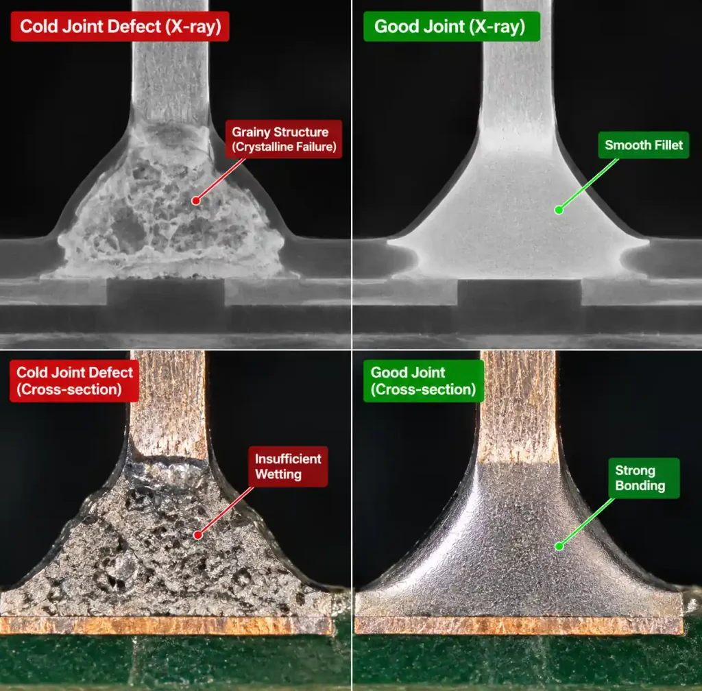
Common Defects and Prevention
Cold joints in selective soldering occur when:
- Preheat is insufficient (board still <100°C when solder arrives)
- Dwell time is too short (<2 seconds)
- Nozzle temperature drifts below 250°C
Prevention: Validate thermal profiles on trial boards before production. Use thermocouples to measure joint temperature during the first 5 cycles.
Solder bridges in wave soldering happen when:
- Board spacing between through-holes <0.8mm (solder bridges the gap)
- Solder pot temperature >290°C (solder becomes too fluid)
Prevention: Design for >1.0mm spacing where possible; maintain pot at 260–280°C.
Insufficient solder in selective soldering results from:
- Nozzle clogging (solder dross accumulation)
- Solder pot level too low
Prevention: Change solder pot every 100–150 hours of operation; check solder level before each shift.
Frequently Asked Questions
Q: Can I use selective soldering for 100% THT boards?
A: Yes, but it’s economically irrational. Your cost per unit will be 3–5x higher than wave soldering. Reserve selective soldering for boards where the benefit (SMT protection, rework reduction) justifies the cost.
Q: Will selective soldering damage BGA components next to through-hole connectors?
A: Minimal risk if proper preheat zones are set. BGA sees ~150°C max; a well-tuned selective system keeps BGAs 2–3cm away from the primary solder nozzle, minimizing thermal impact. Confirm with thermal imaging on trial boards.
Q: How do I choose a manufacturer with strong selective soldering capability?
A: Request data on their nozzle types, preheat uniformity (±10°C tolerance), CAD validation process, and defect rates specifically for mixed boards. Defect rate <1% for selective soldering is typical; <0.5% indicates excellence.
Q: Is rework easier with selective or wave soldering?
A: Selective soldering rework is simpler—you re-solder individual joints without exposing the whole board. Wave soldering rework requires either hand-soldering or re-running through the wave (risking SMT damage). Selective soldering wins here.
Q: Can I mix boards from different designs in a single wave run?
A: Yes, using pallets or masking. Selective soldering requires individual program setup per design, so mixing is less practical—better to batch by design.
Conclusion
Selective soldering is not a universal replacement for wave soldering; it’s a specialized tool for a specific job: mixed-technology boards where SMT components coexist with through-hole connectors or high-reliability joints. For pure through-hole production, wave soldering remains the speed and cost leader. The decision tree is simple—if your board has SMT components on the underside, and you’re soldering through-holes, selective soldering protects your investment and improves yield. If it’s all through-hole, wave soldering delivers faster turnaround and lower unit cost. Choose based on your board architecture, not habit.
For complex assemblies or low-volume custom designs, partner with a manufacturer that offers both capabilities and can model your costs accurately across different process scenarios. Andwin Circuits’ mixed-technology expertise spans both selective and wave soldering—we’ll help you optimize for your application. Learn more about our PCB assembly services.