12 questions about PCB impedance design, easily help you understand impedance
Engineers have all come into contact with impedance, but few engineers can explain impedance clearly. Impedance seems simple, but it is actually difficult to express.
Below we use a quick question and answer method to help you understand impedance easily!
01 Q: What is impedance?
A: In a circuit with resistance, inductance and capacitance, the obstruction to alternating current is called impedance. Impedance is often represented by Z. Impedance consists of resistance, inductive reactance and capacitive reactance, but it is not a simple addition of the three. The unit of impedance is ohm.
Impedance in PCB refers to the electrical impedance between wires, power supplies, loads and other components on the circuit board. PCB impedance control is an important part of designing PCB circuit boards to ensure the performance and stability of the circuit board. In high-speed circuit design, it is crucial to maintain proper impedance because improper impedance can cause serious noise interference to the signal.
02 Q: What is single-ended impedance?
A: Single-ended impedance is a type of characteristic impedance, which refers to the impedance of a single signal line in a circuit. In single-ended transmission, the signal is transmitted through a single signal line.
03 Q: What is differential impedance?
A: The differential signal line structure is used to control impedance. Two signal waveforms with opposite polarities are input to the driving end, transmitted by two differential lines, and processed by subtraction at the receiving end. This method is used to improve signal integrity and noise resistance in high-speed digital-analog circuits.
04 Q: What is coplanar impedance?
A: Coplanar impedance is the test impedance when the signal line is transmitted between GND/VCC. Coplanar waveguide is a common planar structure conductor line in high-frequency and microwave circuits. Coplanar impedance is related to factors such as the geometry of the waveguide, conductor width, and dielectric parameters. By adjusting these factors, the propagation characteristics of electromagnetic waves in the coplanar waveguide can be controlled. The size of the coplanar impedance determines the propagation characteristics of electromagnetic waves in the coplanar waveguide.、
05 Q: Why is the single-ended impedance controlled at 50 ohms?
A: 50 ohms is the industry default value, which has the advantages of easy processing and low loss, but it is not necessary. It depends on the interface. For example, 75 ohms is the standard for remote communication. When cables and antennas use 75 ohms, they need to match the PCB line impedance. Special chips can reduce impedance by improving driving capability, improving EMI and crosstalk suppression. For example, Intel requires impedance control at 37 ohms, 42 ohms or even lower.
06 Q: Why is the differential impedance controlled at 100 ohms?
A: The setting of differential impedance and single-ended impedance has a certain historical evolution and application background. The determination of these impedance values is mainly to meet the needs of specific interfaces and chips to ensure stable signal transmission and good electrical performance. The common impedance value is 100 ohms, and there are also 90 ohms and 85 ohms. The setting of these impedance values can reduce signal reflection, interference and distortion, and improve signal transmission efficiency.
07 Q: Why do differential lines have to be routed in parallel?
A: Differential lines are usually designed with parallel routing to improve anti-interference ability and maintain impedance continuity. This design keeps the coupling degree between the two lines unchanged to ensure impedance continuity.
However, the definition of differential lines does not require parallelism. When parallel routing design is not adopted, it is necessary to ensure that the spacing is greater than 5W, the impedance of the single line is consistent, and the external interference is small. In this way, non-parallel routing can be achieved without coupling two lines.
In the test fixture, the differential line is usually single-ended routing with an impedance control of 50 ohms. Use flying wires or coaxial lines to connect the two lines. As long as they are finally converged to the receiving end, differential transmission can also be performed.

08 Q: Is it okay for the differential lines to be unequal in length?
A: No, the most important physical rule requirement for differential lines is equal length.
I
t is crucial that the differential lines are equal in length because the receiving end performs differential operations on the signals of the two lines. The signal is a trapezoidal wave, and unequal length lines will cause phase errors, which may cause transmission errors. The ideal signal should be peak to trough, but unequal length lines may cause a phase difference of up to 180 degrees, causing transmission errors.
Even if the phase difference is small, such as 30 degrees, it will seriously affect the eye diagram, convert the differential mode component into the common mode component, and reduce the common mode interference immunity. Therefore, the equal length of differential lines is a key indicator, and the error is usually required to be no more than 5mil, with a maximum allowable error of 10mil.
09 Q: Can differential pairs be routed on different layers?
A: Yes, it is possible to use the upper and lower layers for routing, and in theory this method is better than routing on the same layer. First, BGA routing is easier to achieve. More importantly, by distributing differential lines on different layers, the influence of the glass fiber effect can be greatly reduced.
However, in actual engineering, due to the limitations of processing technology, random errors may occur in the routing of different layers, resulting in the inability of the upper and lower layers to overlap accurately. This error may have a serious impact on the performance of the differential line, so this routing method has certain defects.
10 Q: What affects impedance in high-speed PCB design?
A:
- Line width: Impedance Line width is inversely proportional to impedance. The thinner the line width, the higher the impedance, and the thicker the line width, the lower the impedance.
- Copper foil: The thickness of copper foil is inversely proportional to impedance. The thicker the copper thickness, the lower the impedance, and the thinner the copper thickness, the higher the impedance.
- Line spacing: The spacing is proportional to the impedance. The larger the spacing, the greater the impedance. The smaller the spacing, the smaller the impedance.
- Coplanarity: The spacing of the impedance line conductor is proportional to the impedance. The larger the spacing, the greater the impedance. The smaller the spacing, the smaller the impedance.
11 Q: What factors affect the impedance of PCB plate selection?
A:
- Dielectric thickness: The dielectric thickness is proportional to the impedance. The thicker the dielectric, the higher the impedance. The thinner the dielectric, the lower the impedance.
- Dielectric constant: The dielectric constant is inversely proportional to the impedance. The higher the dielectric constant, the lower the impedance. The lower the dielectric constant, the higher the impedance.
- Solder mask thickness: The solder mask thickness is inversely proportional to the impedance. Within a certain thickness range, the thicker the solder mask thickness, the lower the impedance. The thinner the solder mask thickness, the higher the impedance.
12 Q: Which tool is the most convenient for impedance calculation?
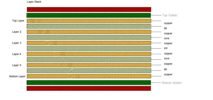
A: Of course it is Huaqiu DFM! Huaqiu DFM impedance tool automatically generates stackup diagrams, supports calculation of a certain impedance individually and all impedances, and also supports inverse calculation function. The calculated impedance data can be exported and saved, and the impedance calculation diagram and stackup diagram can be exported at the same time for user archiving convenience.


