PCB design tips: fewer holes, fewer detours, less automation…
1.Familiarity with factory manufacturing processes
In this era of fabless IC companies, it is not surprising that many engineers are not aware of the production steps and chemical treatment processes for PCBs manufactured based on their design files. However, this lack of practical knowledge often leads novice engineers to make unnecessary and more complex design decisions.
Does the design really need to be that complicated? Can’t a larger grid be used for routing to reduce board costs and improve reliability? Other mistakes that novice designers tend to make include unnecessary small via sizes and blind and buried vias. Those advanced via structures are a weapon for PCB designers, but their effectiveness is highly situational. Although they are available tools, they do not mean that they must be used.
A blog post by PCB design expert Bert Simonovich talks about the issue of via size ratios: “A 6:1 aspect ratio via ensures that your board can be manufactured anywhere.” For most designs, with a little thought and planning, you can avoid those high-density (HDI) features and save costs again and improve the manufacturability of your design.
The physics and fluid dynamics required to plate copper on those ultra-small or dead-ended vias are not something all PCB foundries are good at. Remember, just one bad via can ruin the entire board; if your design has 20,000 vias, you have 20,000 chances of failure. Use HDI vias unnecessarily, and the failure rate will immediately soar.
2.Schematics can simplify design tasks
Sometimes it seems like a waste of time to draw a schematic just to design a simple circuit board; especially if you have already completed one or two designs. But for those who are designing PCBs for the first time, drawing a schematic can also be a daunting task. Skipping the schematic is a common strategy for both new and moderately experienced designers, but starting with a complete schematic to reference and developing your routing helps ensure that your routing connections are complete; here are the reasons.
First, the schematic is a visual representation of the PCB circuit that conveys multiple levels of information; sub-areas of the circuit are detailed over several pages, and components that correspond to each other in function can be placed in close proximity, regardless of their final physical layout. Second, because the schematic symbols indicate each pin of each component, it is easy to check for unconnected pins; in other words, the schematic helps you make a quick visual determination to ensure that the circuit is complete, regardless of whether the formal rules for describing the circuit are being followed.
Having a schematic to use as a base template when designing a PCB can simplify the routing task. Use the schematic symbols to complete the links, and you overcome routing challenges without having to think about those connections again and again; finally, you save design re-spins by catching routing connections that were missed in the first revision.
3.Use auto-routers but don’t rely on them
Most professional-grade PCB CAD tools have auto-routers, but unless you are a professional PCB designer, auto-routers can only be used to get the design through the preliminary test at best; for PCB circuit links, auto-routers are not a one-click solution, and you should still know how to route manually.
Auto-routers are highly configurable tools. To fully play their role, the parameters of the routers must be carefully and thoughtfully set for each task, and even each module on a single PCB must be considered individually. In short, there is no appropriate basic universal default value.
When you ask an experienced design engineer: “Which auto-routers are the best?” They will answer: “The thing between the two ears (eyes);” and they are serious. The routing process is more like an art like an algorithm, which is heuristic in itself, so it is very similar to the traditional backtracking algorithm.
Backtracking algorithms are great for finding solutions, especially in situations where path selection is limited, such as mazes or puzzles; but in an open, unrestricted situation, such as a PCB with pre-placed components, backtracking algorithms cannot play their strengths in finding optimized solutions. Unless the constraints of the autorouter are carefully fine-tuned by an engineer, the finished routing still needs to be manually checked for weaknesses in the backtracking algorithm results.
Trace size is another problem point. The autorouter cannot be 100% sure how much current you intend to pass through a trace, so it cannot help you determine how wide the trace should be; as a result, most autorouters produce trace widths that are not up to specification.
When you consider using an autorouter, ask yourself, “After I set up the autorouter constraints for the board, and even for every trace on the schematic, how much time do I have left to manually route?” Experienced design engineers focus most of their energy on initial part placement, and almost half of their entire design time is dedicated to optimizing component placement in three areas:
● Routing simplification—minimizing crossing of rat’s nests, etc.
● Component proximity—the shorter the better.
● Signal timing considerations.
Old-timers often use a hybrid approach to routing—hand-routing critical traces, fixing their positions, and then using the autorouter to handle non-critical traces; auto-routing regions in the design help manage “runaway” in the routing algorithm, and this approach can sometimes achieve a good compromise between the controllability of manual routing and the speed of auto-routing.
4.Consider board size and current
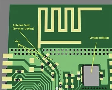
Most people who work in electronics design know that, like a river flowing along a channel, flowing electrons may encounter choke points and bottlenecks; this is directly applied to the design of automotive fuses. By controlling the thickness and shape of the traces (U-bend, V-bend, S-shape, etc.), the fuse can be calibrated to blow at the choke point when the current is overloaded.
The problem is that design engineers occasionally encounter similar electrical choke points in their PCB designs; for example: using 90-degree bends where two steep 45-degree bends will work; when the bend is greater than 90 degrees, using zigzag shapes. At best, those wires will only slow down the signal propagation speed; at worst, they will blow at the resistance point like an automotive fuse.
5.Avoid the risk of slivers
Slivers are a manufacturing error that can be best managed through proper circuit board design (as shown in Figure 1); to understand the sliver problem, we need to review the chemical etching process. Chemical etching is meant to break up unwanted copper, but if the etched portion is particularly long, thin, and flaky, those shapes can sometimes lift off in one piece before they are fully broken down; such fragments float in the chemical solution and can land randomly on another board.
In this case, the narrow shield between the traces is safe for the circuit substrate.
There is also the risk that the fragment will remain on the original board; if the fragment is narrow enough, the acid bath may eat away enough copper underneath to partially lift off the fragment. The fragment will then float around the board like a flag, eventually landing on that board and shorting out other traces.
So where do you look for potential fragments? And how can you avoid them? When routing a PCB, it is best to avoid leaving very narrow areas of copper traces ; such areas are usually caused by crossing traces and pad gaps and filling planes . Set the minimum copper width to be larger than the minimum allowed by the manufacturer, and your design should not have this problem. The standard minimum etch width is 0.006 inches.
A very narrow crack risk area, such as the case in the original design file in the figure, can peel uncontrollably during manufacturing, causing shorts and yield issues.
In this case, chemical etching changes the shape/size of the narrow crack fill; unexpected debris or floating objects are generated when the crack peels.
6.Pay attention to DRC
Autorouter settings are usually targeted at design functions, while Design Rule Checkers (DRCs) are generally used to capture the manufacturer’s design constraints; although the setup process is also cumbersome, it is much better than that of autorouter. Most design teams will eventually establish a set of design rules with the goal of standardizing bare board production costs, maximizing yields, and making assembly, inspection, and testing as consistent as possible.
In addition to benefiting design, these design rules – by keeping the design within predefined manufacturing constraints – also help to establish consistency in the procurement department; if the price of circuit board manufacturing is consistent, procurement can usually reduce the number of specific PCB manufacturing agreements that need to be maintained.
To address all of these issues, many PCB design tools have built-in DRCs—some tools call them “constraint managers”—that interactively flag design violations as you edit; and once you’ve set up DRC rules for your chosen manufacturer, be prepared to take errors seriously.
DRC tools are generally conservative in their design, and they can err on the side of reporting possible errors, which you must judge; sifting through hundreds of “possible” issues can be tedious, but do it anyway. Hidden in this list of issues may be the reason why your first tapeout is doomed to fail. Beyond that, if your design triggers a large number of possible errors, your routing methods need improvement.
Dave Baker, a board design engineer at Sunstone Circuits with over two decades of experience, advises, “Take the time to understand and properly set up the constraint system provided by your routing tool and review all levels of constraints; constraint tools can be powerful and flexible, but can also be confusing and dangerous. Incorrect constraints can easily lead to a defective or unmanufacturable board, and errors in constraint setup can easily limit or disable DRC.”
He gives an example: “What can happen is that the DRC passes every time, but the board is still unmanufacturable or non-functional. I have seen this happen before, and the design team was happy because the board passed the DRC check, but the first batch of products went up in smoke as soon as it was put on the test bench; to track down the cause of the failure, the team went back to the CAD tool’s constraint manager; the constraint manager has no design awareness and will let you do anything, no matter how bad it is.”
For example, Sunstone Circuits receives quote requests almost every day for board designs that we could easily build, except in some key areas, where the design tolerances and clearances are greatly compressed. This situation forces PCB foundries (such as Sunstone) to deliver the bad news: we can’t make the board because the tolerances are beyond our capabilities; or we can make the board, but at a premium and with yield risks. Those customers will benefit from designing with the capabilities of a specific manufacturer in mind.
7.Get to know your existing foundry partners
After discussing DRC settings, this last PCB design tip is almost – but not completely – redundant; in addition to helping you set up DRC rules correctly, you can get some additional pre-shipment assistance by understanding the manufacturer your board design will be sent to.
Good foundries will provide some pre-order assistance and suggestions, including how to process your design to reduce design iterations, reduce problems encountered when debugging on the test bench, and improve board production yield. Hugo, a PhD student at Carnegie-Mellon University, made the following comments in a blog post on understanding manufacturers:
“Each manufacturer has its own specifications, such as minimum trace width, spacing, number of layers, etc. Before starting the design, you should consider your requirements and find a manufacturer that can meet them. Your needs also include the PCB material grade, which ranges from FR-1 (paper-phenolic resin mixture) to FR-5 (fiberglass and epoxy resin); most PCB prototype manufacturers use FR-4, but FR-2 is also commonly used in a large number of consumer applications. The type of material affects the strength, durability, moisture absorption and flame retardancy (FR) of the board.”
Understanding the PCB process and what process and production methods your manufacturer will use can help you make better design decisions; visit your preferred manufacturing service provider and see the process in person, you may be surprised. Also, make good use of design for manufacturability (DFM) tools before sending the design drawings for production.
Summary
If you have mastered all seven of the above basic tips, you are on the road to fast, reliable, professional quality PCBs.
Use all the design tools provided by your CAD tool wisely, including auto-placement and auto-routing, but be patient and careful when setting up the auto-router to achieve good auto-routing results. Don’t rely on the auto-router to do anything other than routing; if necessary, adjust the trace size manually to ensure the current in the design is appropriate. And no matter what, always trust the flying wires. Until these are fully done, your circuit design will not be successful.