2 layer metal core pcb
What is MCPCB?
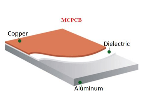
Metal Core Printed Circuit Board (MCPCB), also known as insulated metal substrate (IMS) PCB and thermal PCB,as opposed to traditional FR4,is a PCB based on a metal material used for the heat dissipation part.During the operation of a circuit board,heat is generated by certain electronic components.The purpose of the metal is to transfer this heat from critical board components to less important areas,such as metal heat sinks or metal cores.The most commonly used metals in MCPCB manufacturing are aluminum,copper and steel alloys.
Aluminum has good heat transfer and dissipation capabilities and is relatively inexpensive.Copper offers better performance but is relatively more expensive.Steel, on the other hand,can be divided into regular steel and stainless steel,it is harder than aluminum and copper but has lower thermal conductivity.
Users can choose their base core material based on different applications.Among all these metals,considering thermal conductivity, rigidity, and cost, aluminum is the most economical choice.Therefore,the core material of a standard Metal Core PCB (MCPCB) is made of aluminum.
MCPCBs consist of a conductive layer,a thermal insulation layer board,and a metal substrate layer.
Double Layers MCPCB
A two-layer MCPCB consists of a metal core (usually made of aluminum, copper, or iron alloy) and two copper conductive layers on the same side. The metal base is located at the bottom of the entire MCPCB, unlike a double-sided MCPCB where the two copper layers are placed on each side of the metal core. The assembly can only be done on the top surface.
In contrast to a single-layer MCPCB, a two-layer MCPCB requires an additional lamination step to bond the thermal conductive layer and the metal core (also known as the metal substrate) together. This structure requires more technical expertise and experience compared to regular FR4 PCBs to laminate the two layers with the metal core.
The processing steps of embedding the metal base in the MCPCB are more complex, as after drilling holes on the metal base, it is necessary to fill the holes to isolate it from the circuit.

Double Layer MCPCB Structure
Applications
- Office automation equipment
- Power modules,such as power rectifiers, inverters, etc
- Audio equipment,such as balanced amplifiers, preamplifiers, etc
- Power controllers and electronic regulators in automobiles
- Communication electronic devices,such as transmitter circuits and high-frequency amplifiers
Double-Sided MCPCB
Similar to two-layer metal-based PCB, double-sided metal core PCB also has two layers of copper conductors, but the metal core is positioned between the two conductors. Therefore, there are conductors (traces) on both sides of the metal core, and they are interconnected through vias. Hence, it is called “double-sided metal core PCB,” and you can mount SMD components on both the top and bottom sides.
Unlike single-sided metal-based PCB, double-sided metal core PCB requires an additional lamination step to bond the patterned thermal conductive layer onto the metal core (also known as the metal substrate). However, sometimes, certain raw material suppliers for metal coverings provide pre-laminated sheets.
Compared to regular FR4 material, this structure requires more technical expertise and experience to laminate the two layers with the metal core.

Double-Sided MCPCB Structure
Applications
- Line Reactor
- Industrial Control
- Regulator
- Power Supply
- Converter
- HVAC System
- Hard Disk Drive
- Automotive Dashboard
- Transportation System
- UPS System
Design and Manufacturing of Metal Core PCBs
Metal core PCBs are not very common in consumer products, but they abound in industry, aerospace, lighting systems, power electronics, and other fields that require high reliability. High-power systems generate a lot of heat and need to remove it quickly to prevent component failure. Similarly, low-power systems may be exposed to high heat and also need to remove it quickly to prevent damage to the board and components.
Metal core PCB design (including DFM) follows many of the same basic design rules as typical PCBs on FR4. If you are designing a new product in any of these fields, you may need to use a metal core board to control temperature. In this article, I will briefly explain the construction of metal core PCBs and some important design points to consider before planning to use metal core PCB design. These boards come with special manufacturing requirements, but the right design company can help cope with these requirements and ensure that the PCBs can be mass-produced.
Applications of Metal Core PCB Designs
Metal core PCBs can find their place in almost any application where a device generates a lot of heat when it is running. These boards are not an ideal replacement for ceramics because they are a lower cost option and they offer higher thermal conductivity to remove heat from important components. They are often a starting point when looking for a circuit board for a system with strong heat dissipation capabilities. Some applications of metal core PCBs include:
LED lighting units: Boards with high-power LEDs are often manufactured on metal core PCBs. These boards provide a sturdy base for high-power LEDs (SMD and through-hole) while dissipating high heat into the metal core board.
Power conversion and management: Hybrid vehicles, industrial equipment, **** telecommunications equipment, and municipal power distribution systems all operate at high power. Metal core PCBs are common in these fields.
Solar equipment: Solar equipment needs to be particularly rugged and operate at high temperatures as well as high DC voltages/currents. Similar PCB designs can be implemented in geothermal facilities.
Military (e.g., submersibles, aircraft): Metal core PCBs can quickly dissipate heat, keeping electronics away from electronic devices that may be located near high heat sources such as engines or exhaust systems.
There are many other areas where high reliability and structural rigidity are also critical, making metal core boards an excellent choice. Once you start looking at the stackup and layout requirements for these boards, it becomes less obvious how to actually design them. Can you do multi-layer metal core boards? Can you do double-sided? How do you handle vias during manufacturing? These are all important questions related to the DFM of metal core PCBs.