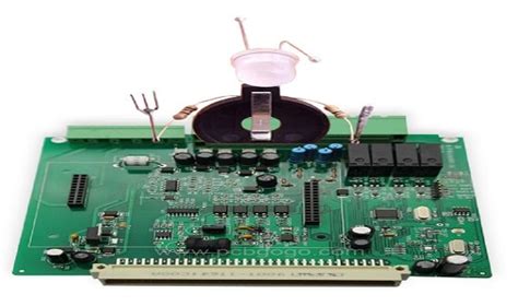
Engine controller pcb assembly
Importance Of Quality Control In Engine Controller PCB Assembly
The importance of quality control in engine controller PCB assembly cannot be overstated, as it plays a pivotal role in ensuring the reliability and performance of automotive engines. Engine controllers, often referred to as Engine Control Units (ECUs), are sophisticated electronic devices that manage various engine functions, including fuel injection, ignition timing, and emission control. The printed circuit board (PCB) within these controllers serves as the backbone, housing the intricate network of electronic components that enable the ECU to perform its critical tasks. Consequently, the assembly of these PCBs demands meticulous attention to detail and rigorous quality control measures.
To begin with, the complexity of modern engine controllers necessitates a high degree of precision during PCB assembly.
Any deviation from the specified design can lead to malfunctions, which may compromise engine performance or even result in catastrophic failures. Therefore, quality control processes are essential to verify that each component is correctly placed and soldered onto the PCB. Automated optical inspection (AOI) systems are commonly employed to detect any misalignments, soldering defects, or missing components. By identifying and rectifying these issues early in the assembly process, manufacturers can prevent potential problems from escalating into more significant concerns.
Moreover, the harsh operating conditions to which engine controllers are subjected further underscore the need for stringent quality control.
These devices must withstand extreme temperatures, vibrations, and exposure to various chemicals. Ensuring that the PCB assembly is robust and reliable is crucial for maintaining the longevity and functionality of the engine controller. Environmental stress screening (ESS) and thermal cycling tests are often conducted to simulate these conditions and assess the durability of the assembled PCBs. Through these tests, manufacturers can identify and address any weaknesses in the assembly, thereby enhancing the overall reliability of the engine controller.
In addition to the technical aspects, regulatory compliance is another critical factor driving the importance of quality control in engine controller PCB assembly.
Automotive manufacturers must adhere to stringent industry standards and regulations, such as ISO/TS 16949 and the Automotive Electronics Council (AEC) guidelines. These standards mandate rigorous quality control procedures to ensure that the electronic components used in vehicles meet the highest safety and performance criteria. Non-compliance can result in costly recalls, legal liabilities, and damage to the manufacturer’s reputation. Therefore, implementing comprehensive quality control measures is not only a technical necessity but also a regulatory imperative.
Furthermore, the increasing integration of advanced technologies,
such as artificial intelligence and machine learning, into engine controllers adds another layer of complexity to PCB assembly. These technologies require the incorporation of sophisticated sensors, processors, and communication modules, all of which must be seamlessly integrated onto the PCB. Quality control processes must evolve to keep pace with these advancements, employing cutting-edge inspection and testing techniques to ensure that the assembled PCBs can support the enhanced functionalities of modern engine controllers.
In conclusion, the importance of quality control in engine controller PCB assembly is multifaceted, encompassing precision in assembly, durability under harsh conditions, regulatory compliance, and the integration of advanced technologies. By implementing rigorous quality control measures, manufacturers can ensure that their engine controllers perform reliably and safely, thereby contributing to the overall efficiency and longevity of automotive engines. As the automotive industry continues to evolve, the role of quality control in PCB assembly will remain a cornerstone of ensuring the success and reliability of engine controllers.
Latest Trends In Engine Controller PCB Assembly Technology
The field of engine controller PCB (Printed Circuit Board) assembly has witnessed significant advancements in recent years, driven by the relentless pursuit of efficiency, reliability, and performance in automotive and industrial applications. As technology continues to evolve, several key trends have emerged, shaping the future of engine controller PCB assembly and setting new standards for the industry.
One of the most notable trends is the increasing integration of advanced materials and components.
Modern engine controllers demand high levels of precision and durability, which has led to the adoption of materials such as high-temperature laminates and advanced soldering techniques. These materials not only enhance the thermal management capabilities of the PCBs but also improve their overall reliability and lifespan. Consequently, manufacturers are now able to produce engine controllers that can withstand the harsh operating conditions typically encountered in automotive and industrial environments.
In addition to material advancements, the miniaturization of components has become a critical focus area.
As engines become more sophisticated and compact, the need for smaller, yet more powerful, engine controllers has grown. This has driven the development of miniaturized components, such as microcontrollers and power management ICs, which can be densely packed onto PCBs without compromising performance. The trend towards miniaturization is further supported by advancements in surface-mount technology (SMT), which allows for the precise placement of tiny components on the PCB, thereby maximizing space utilization and enhancing overall functionality.
Another significant trend is the increasing use of automation in the PCB assembly process.
Automation technologies, such as robotic pick-and-place machines and automated optical inspection (AOI) systems, have revolutionized the manufacturing process by improving accuracy, reducing human error, and increasing production speed. These automated systems are capable of handling complex assembly tasks with high precision, ensuring that each PCB meets stringent quality standards. Moreover, the integration of machine learning algorithms into these systems has enabled real-time monitoring and adaptive control, further enhancing the efficiency and reliability of the assembly process.
The rise of the Internet of Things (IoT) has also had a profound impact on engine controller PCB assembly.
IoT-enabled engine controllers are now capable of real-time data collection and communication, allowing for enhanced monitoring and diagnostics. This connectivity facilitates predictive maintenance, enabling early detection of potential issues and reducing downtime. To support this functionality, PCBs are being designed with integrated communication modules, such as Wi-Fi and Bluetooth, as well as advanced sensors that can capture a wide range of operational parameters. The incorporation of IoT technology into engine controllers not only improves their performance but also opens up new possibilities for remote management and control.
Furthermore, the push towards sustainability and environmental responsibility has influenced the design and manufacturing of engine controller PCBs.
Manufacturers are increasingly adopting eco-friendly practices, such as using lead-free solder and recyclable materials, to minimize the environmental impact of their products. Additionally, energy-efficient design principles are being applied to reduce the power consumption of engine controllers, thereby contributing to overall energy savings and reducing the carbon footprint of automotive and industrial systems.
In conclusion, the latest trends in engine controller PCB assembly technology reflect a dynamic and rapidly evolving landscape. The integration of advanced materials, miniaturization of components, automation, IoT connectivity, and sustainable practices are all driving the industry forward. As these trends continue to develop, they promise to deliver even greater levels of efficiency, reliability, and performance, ultimately benefiting a wide range of applications in the automotive and industrial sectors.
Common Challenges In Engine Controller PCB Assembly And How To Overcome Them
Engine controller PCB assembly is a critical process in the manufacturing of automotive electronics, requiring precision and adherence to stringent quality standards. However, this process is fraught with challenges that can impact the performance and reliability of the final product. Understanding these common challenges and implementing strategies to overcome them is essential for ensuring the success of engine controller PCB assemblies.
One of the primary challenges in engine controller PCB assembly is the complexity of the design.
Engine controllers often require intricate circuitry to manage various engine functions, such as fuel injection, ignition timing, and emission control. This complexity can lead to difficulties in layout design, component placement, and routing. To address this, it is crucial to employ advanced design software that can handle complex schematics and provide accurate simulations. Additionally, involving experienced engineers in the design phase can help identify potential issues early and optimize the layout for manufacturability.
Another significant challenge is the selection and sourcing of components.
Engine controllers must operate reliably under harsh conditions, including extreme temperatures, vibrations, and exposure to contaminants. Therefore, selecting components that meet automotive-grade standards is essential. However, sourcing these high-quality components can be challenging due to supply chain constraints and lead times. To mitigate this, establishing strong relationships with reputable suppliers and maintaining a buffer stock of critical components can help ensure a steady supply and reduce the risk of production delays.
Thermal management is also a critical concern in engine controller PCB assembly.
The high power density and continuous operation of engine controllers generate significant heat, which can affect the performance and longevity of the components. Effective thermal management strategies, such as using heat sinks, thermal vias, and appropriate PCB materials, are necessary to dissipate heat efficiently. Additionally, conducting thorough thermal analysis during the design phase can help identify potential hotspots and optimize the thermal performance of the PCB.
Soldering defects, such as cold joints, solder bridges, and voids, are common issues that can compromise the reliability of engine controller PCBs.
These defects often arise from improper soldering techniques, inadequate flux application, or incorrect reflow profiles. To overcome these challenges, it is essential to implement stringent process controls and quality assurance measures. Utilizing automated optical inspection (AOI) and X-ray inspection systems can help detect soldering defects early in the assembly process, allowing for timely corrective actions. Moreover, providing comprehensive training to assembly personnel on best soldering practices can significantly reduce the occurrence of defects.
Electromagnetic interference (EMI) is another challenge that can affect the performance of engine controller PCBs.
The high-frequency signals and switching operations within the controller can generate EMI, which can interfere with other electronic systems in the vehicle. To mitigate EMI, implementing proper grounding and shielding techniques is crucial. Additionally, designing the PCB layout to minimize signal loops and using differential signaling for high-speed data lines can help reduce EMI susceptibility.
Finally, ensuring the reliability and durability of engine controller PCBs requires rigorous testing and validation.
Environmental stress testing, such as thermal cycling, vibration testing, and humidity exposure, can help identify potential failure modes and ensure the PCB can withstand real-world conditions. Implementing a robust testing protocol and continuously monitoring the performance of the PCBs in the field can provide valuable feedback for ongoing improvements.
In conclusion, while engine controller PCB assembly presents several challenges, adopting a proactive approach and leveraging advanced technologies can significantly enhance the quality and reliability of the final product. By addressing design complexity, component selection, thermal management, soldering defects, EMI, and rigorous testing, manufacturers can overcome these challenges and deliver high-performance engine controllers that meet the demanding requirements of the automotive industry.
Step-By-Step Guide To Engine Controller PCB Assembly Process
The process of assembling a Printed Circuit Board (PCB) for an engine controller is a meticulous and intricate task that demands precision and attention to detail. This step-by-step guide aims to elucidate the various stages involved in the assembly process, ensuring a comprehensive understanding of each phase.
Initially, the process begins with the design and layout of the PCB.
Engineers utilize specialized software to create a schematic diagram, which serves as a blueprint for the circuit. This schematic is then translated into a layout that specifies the placement of components and the routing of electrical connections. Once the design is finalized, the layout is sent to a manufacturer to produce the physical PCB.
Upon receiving the manufactured PCB, the next step involves the procurement of components.
These components, which include microcontrollers, resistors, capacitors, and other essential elements, must be sourced from reliable suppliers to ensure quality and compatibility. It is crucial to verify that all components meet the specified requirements and are free from defects.
Following the procurement phase, the assembly process commences with the application of solder paste.
Solder paste, a mixture of powdered solder and flux, is applied to the PCB using a stencil that aligns with the pads where components will be placed. This step is critical as it ensures that the components will adhere properly to the board during the soldering process.
Subsequently, the components are placed onto the PCB.
This task is typically performed using automated machines known as pick-and-place machines, which accurately position each component onto the corresponding pads. For components that require manual placement, skilled technicians use tweezers and microscopes to ensure precise alignment.
Once all components are in place, the PCB undergoes a reflow soldering process. During this stage, the board is passed through a reflow oven where it is gradually heated to melt the solder paste, creating secure electrical connections between the components and the PCB. The temperature profile of the oven is carefully controlled to prevent damage to sensitive components.
After reflow soldering, the PCB is inspected for any defects or misalignments.
Automated optical inspection (AOI) systems are commonly used to detect issues such as solder bridges, missing components, or incorrect placements. Any identified defects are rectified through manual rework, ensuring the integrity of the assembly.
The next phase involves the testing of the assembled PCB.
Functional testing is conducted to verify that the engine controller operates as intended. This may include running diagnostic software, simulating engine conditions, and measuring electrical parameters. Any anomalies detected during testing are addressed through troubleshooting and repair.
Following successful testing, the PCB undergoes conformal coating to protect it from environmental factors such as moisture, dust, and chemicals. This protective layer is applied using methods such as spraying, dipping, or brushing, and is allowed to cure before the final inspection.
Finally, the assembled and tested PCB is ready for integration into the engine controller housing.
This involves mounting the PCB into its enclosure, connecting any necessary wiring, and performing a final round of functional tests to ensure the complete assembly meets all specifications.
In conclusion, the assembly of an engine controller PCB is a complex process that requires careful planning, precise execution, and rigorous testing. Each step, from design and component placement to soldering and final inspection, plays a vital role in ensuring the reliability and performance of the engine controller. By adhering to these meticulous procedures, manufacturers can produce high-quality PCBs that meet the demanding requirements of modern engine control systems.